
Installation & Assembly

Modern Forms
www.modernforms.com
Phone (800) 526.2588 • Fax (800) 526.2585
Headquarters/Eastern Distribution Center
44 Harbor Park Drive • Port Washington, NY 11050
Phone (516) 515.5000 • Fax (516) 515.5050
Western Distribution Center
1750 Archibald Ave • Ontario, CA 91761
Phone (800) 526.2588 • Fax (800) 526.2585
Modern Forms retains the right to modify the design of our products at any time as part of the company's continuous improvement program. JULY, 2014
INSTALLATION INSTRUCTION
GILT
PD-51318
PREPARATION
1. Shut o the power at the circuit breaker and remove
existing xture, including the mounting hardware.
2. Carefully unpack your new xture and lay out
all the parts on a clear area. Be careful not to lose
any small parts necessary for installation.
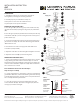
MOUNTING THE FIXTURE (FIG.1)
3. Place the glass (O1) into the ring (P1). Secure them to the top
inside of metal shade (N1) using the long screw (L1) and washer
(M1).
4. Place the glass panel (K1) (frosted side face down) onto the top
of the metal shade (N1). Secure it using the short screws (I1) and
plastic washers (J1).
5. Secure the mounting plate (D1) to the junction box (A1) using
junction box screw (E1). The side of the mounting plate marked
“GND” must face out.
6. Unscrew the set-screw on canopy spider with a at-head
screw-driver (not provided).
7. Adjust the cable wires to desired length and tighten set screws.
8. Adjust the strain relief (Q1) near the wiring holes.
CONNECTING THE WIRES (FIG.2)
9. Connect the transformer input wires to supply wires as shown
in Fig.2, making sure that all wire connectors (C1) are secured.
Cut the two wires marked “24V AC” leaving at least 6” length and
connect to the transformer output wires (red). Make sure that all
wire connectors are secured.
Note: The xture wire has two braided layers.
Strip two layers carefully.
10. If your outlet box has a ground wire, connect it to the xture’s
ground wire. Otherwise, connect the xture’s ground wire directly
to the mounting plate (D1) using the green screw provided. Tuck
wires carefully inside the junction box.
11. Place the canopy (F1) over the mounting plate (D1) and
secure with ball nuts (B1). Thread the ceiling pan (H1) onto the
canopy (F1) clockwise until tight.
FIG.2
Fixture Wires
Black or
Smooth
Fixture Wires
White or
Ribbed
Fixture Wires
Bare Copper
(Ground)
House Wires
Black
(Hot)
House Wires
White
(Neutral)
House Wires
Green or Bare Copper
(Ground)
A1
C1
G1
E1
D1
F1
Q1
B1
H1
I1
J1
K1
L1
M1
N1
O1
P1
FIG.1