
Assembly Instructions


Modern Forms
www.modernforms.com
Phone (800) 526.2588 • Fax (800) 526.2585
Headquarters/Eastern Distribution Center
44 Harbor Park Drive • Port Washington, NY 11050
Phone (516) 515.5000 • Fax (516) 515.5050
Western Distribution Center
1750 Archibald Ave • Ontario, CA 91761
Phone (800) 526.2588 • Fax (800) 526.2585
Modernforms retains the right to modify the design of our products at any time as part of the company's continuous improvement program. MAY, 2014
PREPARATION
1. Shut o the power at the circuit breaker and remove existing xture, including the crossbar.
2. Carefully unpack your new xture and lay out all the parts on a clear area. Be careful not to lose any small parts necessary
for installation.
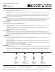
CONNECTING THE WIRES (Fig. 2)
3. Remove screws (C1) from the xture.
4. Connect the transformer input wires to junction box wires as shown in Fig. 2, making sure that all wire connectors (A1) are
secured. If your outlet box has a green or bare copper ground wire (M1), connect the xture’s ground wire to it. Otherwise,
connect the xture’s ground wire directly to the back plate (D1) using the green screw (E1) provided. After wires are connected,
tuck them carefully inside the junction box. *Requires Transformer to be recessed within the junction box
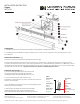
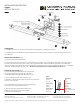
MOUNTING THE FIXTURE (Fig. 1)
5. Secure mounting backplate (D1) to the junction box
(F1) using junction box screws (B1).The side of the
mounting backplate marked “GND” (E1) must face out.
6. Connect the xture’s blue and red wires to the
transformer’s red output wires; blue to red; red to the other red.
Use wire connectors (K1).
7. Place the xture’s canopy plate (L1) over the mounting
back plate (D1) and secure with screws (C1).
8. Slide the glass (G1) onto the front bracket (N1).
Mount end caps (H1) to the front bracket with
screws (I1) to secure the glass.
FIG.2
Fixture Wires
Black or
Smooth
Fixture Wires
White or
Ribbed
Fixture Wires
Bare Copper
(Ground)
House Wires
Black
(Hot)
House Wires
White
(Neutral)
House Wires
Green or Bare Copper
(Ground)
INSTALLATION INSTRUCTION
Vogue
WS-3127, WS-3139
FIG.1
N1
G1
L1
K1
B1
J1
D1
A1
F1
M1
E1
C1
H1
I1