
Installation & Assembly

3
INSTALLATION INSTRUCTIONS
PL-77017/PL-77027
modernforms.com
Phone (800) 526.2588
Fax (800) 526.2585
Headquarters/Eastern Distribution Center
44 Harbor Park Drive
Port Washington, NY 11050
Central Distribution Center
1600 Distribution Ct
Lithia Springs, GA 30122
Western Distribution Center
1750 Archibald Avenue
Ontario, CA 91760
1. Shut o the power at the circuit breaker and remove existing xture, including the crossbar.
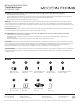
2. Carefully unpack your new xture and lay out all the parts on a clear area. Be careful not to lose any small parts necessary for installation.
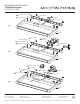
1. Remove the mounting screw (B) from the xture.
2. Drill holes in the wall aligned with the key holes located on the mounting back plate. Insert the plastic anchor (D).
3. Drill a small access hole in the wall behind the xture and pull the house wires through the wall.
4. Fasten the mounting back plate to the wall using the round head wood screws (E) provided.
5. Connect the driver’s wires to house wires as shown in Fig.4, making sure that all wire connectors (A) are secured. If your outlet box has
a green or bare copper ground wire, connect the xture’s ground wire to it. Otherwise, tuck the xture’s ground wire directly to the
xture. After wires are connected, tuck them carefully inside the wall hole.
6. Secure the xture to the mounting back plate using the big mounting screw (B).
1. Replace or install newly slim junction as foundation to enclose all the wiring per code. Use the two at head wood screws (F) provided
to secure the slim junction box (H) on wall properly. Note: the junction box must be recessed about 1/8” into the surface of your wall.
2. Follow step 1 to 6 according to “MOUNT WITHOUT JUNCTION BOX”.
no need to drill a small access hole in the wall.
1. Remove the big mounting screw (B) from the xture.
2. Secure the decorative plate (G) to the mounting back plate by fastening the small mounting screw (C) to the back of the decorative plate.
3. Drill holes in the wall aligned with the key holes located on the mounting back plate. Insert the plastic anchor (D).
4. Fasten the mounting back plate to the wall with the plastic anchors using the round head wood screws (E) provided; make sure to align
the decorative plate to adequately cover the junction box wall opening.
5. Paste the gasket (I) to both end of the xture.
6. Connect the driver’s wires to house wires as shown in Fig.4, making sure that all wire connectors (A) are secured. If your outlet box
has a green or bare copper ground wire, connect the xture’s ground wire to it. Otherwise, tuck the xture’s ground wire directly
to the xture. After wires are connected, tuck them carefully inside the junction box.
7. Secure the xture to the mounting back plate using the big mounting screw (B).
Fixture Wires
Black or
Smooth
Fixture Wires
White or
Ribbed
Fixture Wires
Bare wire
(Ground)
House Wires
Black
(Hot)
House Wires
White
(Neutral)
House Wires
Green or Bare Copper
(Ground)
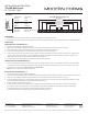
PL-77027:21 1/8"
PL-77017:11"
PL-77027:11"
PL-77027:15 3/4"
3 5/8"
2 3/4"
PL-77017:15"
PL-77027:25"
1 3/8"