
Installation & Assembly

Modern Forms
www.modernforms.com
Phone (800) 526.2588 • Fax (800) 526.2585
Headquarters/Eastern Distribution Center
44 Harbor Park Drive • Port Washington, NY 11050
Phone (516) 515.5000 • Fax (516) 515.5050
Western Distribution Center
1750 Archibald Ave • Ontario, CA 91761
Phone (800) 526.2588 • Fax (800) 526.2585
Modern Forms retains the right to modify the design of our products at any time as part of the company's continuous improvement program. JUNE, 2015 2
INSTALLATION INSTRUCTION
Vessel - LED Wall Mount
WS-W9101, WS-W9102
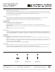
Fixture Wires
Black or
Smooth
Fixture Wires
White or
Ribbed
Fixture Wires
Bare wire
(Ground)
House Wires
Black
(Hot)
House Wires
White
(Neutral)
House Wires
Green or Bare Copper
(Ground)
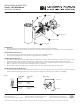
Junction Box
Caulking
Fig.3 Sealing
PREPARATION
- Shut o the power at the circuit breaker and remove existing xture, including the mounting hardware.
- Carefully unpack your new xture and lay out all the parts on a clear area. Be careful not to lose any small parts necessary for installation.
MOUNTING THE FIXTURE (FIG. 1)
1. Remove the mounting screws (C1) from the xture and set aside for re-assembling the xture.
2. Secure mounting backplate (E1) to the Junction box using junction box screws (B1).
CONNECTING THE WIRES (FIG. 2)
3. Connect the electrical wires as shown in Fig. 2, making sure that all wire connectors (A1) are secured. If your outlet box has a green or bare
copper ground wire, connect the xture’s ground wire to it. After wires are connected, tuck them carefully inside the junction box.
4. This xture is dimming with electronic low voltage dimmer switch. If want to use 0-10V dimmer switch as your desire, connect the brown
(BR or +) / blue (BL or -) wires of driver with 0-10V dimmer switch (not provided).
5. Place the xture over the mounting plate (E1) and secure with screws (C1) and gasket (D1) on both top and bottom.
COMPLETING THE INSTALLATION (FIG. 3)
6. To prevent moisture from entering the outlet box and causing a short, use clear caulking (i.e. indoor/outdoor silicone sealant) to outline the
outside of xture backplate where it meets the wall leaving a space at bottom to allow moisture a means to escape (Fig. 3).
Fig. 1
Wire Connector
Junction Box
Junction Box Screw
Mounting Screw
Gasket
Back Plate
A1
E1
D1
B1
C1
Fig. 2