
User manual
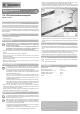

• In sequence, remove the protective foil from every LED strip and glue them to the intended,
previously cleaned installation sites (figure 1, item 1). The LEDs are lit downwards as shown in figure
1, item 2 when the PCD is installed with the “plus side” down.
Figure 1
• Place the cables so that they cannot get into rotating drive parts. Also observe that the vehicle’s
wheels will not touch the cables even when deflected.
Adjusting LED-Strips in Length
• The LED strips can be separated. One of the separation points is shown in figure 1, item 3. To
separate an LED-strip, cut it apart centrally at the desired separating point.
• Solder a suitable cable (not included) to the PCB connection points. Observe the polarity. The red
cable must be soldered to the “+” (plus pole) connection, the black cable to the “-” (minus pole)
connection of the PCB.
• Place the connection cables as described in the section “Installing the LED-Strips”.
Disposal
Dispose of the product according to the applicable statutory provisions at the end of its
service life.
Technical Data
Operating voltage .................................................... 5 to 6 V/DC
Power intake (at 6 V/DC) ......................................... 270 mA
LED-strip dimensions (L x W x H) ........................... 120 x 8 x 2 mm
Cable length (strip to strip) ...................................... 220 mm
Cable length (connection cable) ............................. 290 mm
Weight...................................................................... 20 g
1:10 LED Under-Floor Lighting Set
Item no. 23 80 22
Intended Use
The product serves as effect light for model vehicles and is specifically designed for the 1:10 size. The
LED under-floor light is operated by the receiver power supply and soldered ready for connection. The
LED strips can be separated as desired.
This product complies with the statutory national and European requirements. All company names and
product names are trademarks of their respective owners. All rights reserved.
Scope of Delivery
• 4 LED-strips with 4 LEDs each, self-adhesive
• Operating instructions
Safety Information
Attention! The guarantee/warranty will expire if damage is incurred resulting from
non-compliance with the operating instructions! We do not assume any liability for
consequential damage!
We do not assume any liability for damage to property or personal injury caused by
improper use or the failure to observe the safety instructions! In such cases the
warranty/guarantee will expire.
• The product must not become damp or wet. Danger of short-circuit! Loss of guarantee/warranty!
• This product is not a toy and not suitable for children.
• Attention, LED light: Never look into the LED beam! Never watch directly or with optical instruments!
• Do not leave packaging material unattended. It may become a dangerous toy for children.
• Handle the product with care; impacts, shock or fall even from low heights will damage it.
Connecting the LED Strips
The LED-strips are only designed for operating voltages of 5 to 6 V/DC. Lower voltages will
reduce luminescence. Higher voltages will heat up the LEDs and destroy them over time.
Loss of guarantee/warranty!
The LED-strips are connected to the receiver power supply. If batteries or rechargeable
batteries are used for this, their operating time reduces due to the additional power
requirement of the LEDs.
If a BEC system is used to supply the receiver system (e.g. via a speed controller), this
system, as well as the driving battery, is also subject to additional strain due to the LED
power demand. In either case, observe that the operating times will be reduced.
The maximum power of the BEC system available for servo control will also reduce. It is also
possible that the BEC system is overloaded by the load of the servos and the added LED-
strips. Observe the technical data of the LED-strips and the speed controller used by you.
• Connect the LED connection cable to a free receiver slot with the installed plug. Observe the polarity.
The red cable is “+” (plus pole), the black one “-” (minus pole).
• Alternatively, you may also connect the LED-strips to a switching module (not included in the delivery)
if you wish, and switch it on and off via the remote control.
Installing the LED-Strips
For best visual effects, we recommend that you find the match position before final
attachment of the LED-strips and to initially attach them with transparent adhesive tape
only.
When selecting the assembly sites, ensure that no splash water or lubricant can reach the
LED strips in operation. The LED-strips also must not come into contact with any other
conductive components (e.g. carbon fibre), since there is a danger of short-circuit
otherwise.
In extreme cases, the entire receiver system may fail. Loss of guarantee/warranty! No
liability is assumed for consequential damage.
The installation sites for the LED-strips must be picked so that they cannot be mechanically
damaged in case of accidents (vehicle turning over, etc.).
• Use suitable means to clean the installation site for the LED-strips thoroughly of dust, dirt or
lubricants. Carefully dry the cleaned places.
Operating instructions
Version 01/12
These operating instructions are a publication by Conrad Electronic SE, Klaus-Conrad-Str. 1, D-92240 Hirschau
(www.conrad.com).
All rights including translation reserved. Reproduction by any method, e.g. photocopy, microfilming, or the capture in
electronic data processing systems require the prior written approval by the editor. Reprinting, also in part, is prohibited.
These operating instructions represent the technical status at the time of printing. Changes in technology and
equipment reserved.
© Copyright 2012 by Conrad Electronic SE.