
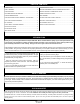
Specifications

Page 7
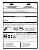
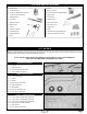
❑ # 2 Phillips Head Screwdriver
❑ 1.5mm Hex Wrench (Optional)
❑ Modeling Knife
❑ Electric or Hand Drill
❑ (1) Fuselage
❑ (2) Motor Mount Straps - Tall
❑ (2) Motor Mount Straps - Short
❑ (4) M3 x 12mm Wood Screws
❑ 5/64” (2mm) Drill Bit
❑ Straight Edge Ruler
❑ Pencil
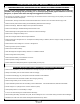
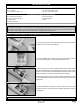
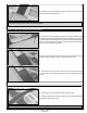
STEP 1A: INSTALLING THE MOTOR - BRUSHLESS WITH IN-LINE GEARBOX
❑ Cut away enough of the plywood motor plate to ensure that your propeller
adapter will not hit it when it's installed later.
❑ Set the two taller motor mounting straps onto the plywood rails. Position
the motor mounting straps in the approximate positions shown.
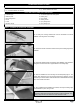
❑ Set your motor onto the motor mounting straps and push it forward so that
the front of the gearbox is just about touching the plywood motor plate. In this
position, when you install your propeller adapter, the front edge of the propeller
adapter will be about 1/4" (6mm) in front of the front of the fuselage.
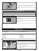
❑ While gently holding the motor in position, adjust the placement of the two
motor mounting straps so they are centered, but not covering any of the motor’s
cooling slots.
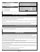
IMPORTANT This section shows the installation of two different types of motors. The rst type shown (in Step 1A) is a brushless
motor with an in-line gearbox. The second type shown (in Step 1B) is a brushless Outrunner direct drive motor. If you're mounting
an Outrunner motor you will need to use mounting screws and washers that match your motor (mounting screws and washers are
not included). Please skip to the step that matches the type of motor that you're going to use.
❑ When satised with the alignment, mark the locations of the four motor
mounting screws, then drill four 5/64" (2mm) diameter pilot holes through the
mounting rails.
IMPORTANT Be careful not to drill through the top of the fuselage.
MOTOR INSTALLATION
YOU'LL NEED THE FOLLOWING PARTS FROM THE KIT:
YOU'LL NEED THE FOLLOWING TOOLS AND SUPPLIES: