
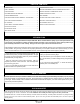
Specifications

Page 5
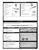
❑ 5 Minute Epoxy
❑ Thin and Thick C/A
❑ # 1 and # 2 Phillips Head Screwdrivers
❑ 1.5mm Hex Wrench (Optional)
❑ Adjustable Wrench
❑ Wire Cutters
❑ Needle Nose Pliers
❑ Modeling Knife
❑ Scissors
❑ Electric or Hand Drill
❑ Assorted Drill Bits
❑ Straight Edge Ruler
❑ Pencil
❑ T-Pins
❑ Builder's Triangle
❑ 220 Grit Sandpaper with Sanding Block
❑ Masking Tape
❑ Paper Towels
❑ Rubbing Alcohol
❑ Epoxy Mixing Sticks
❑ Epoxy Mixing Cups
❑ Soldering Iron
❑ Solder
❑ Heat-Shrink Tubing (Assorted Sizes)
❑ Heat Gun (for Heat-Shrink Tubing)
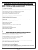
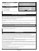
Before you begin assembly, group the parts as we list them below. This will ensure that you have all of the parts before you begin
assembly and it will also help you become familiar with each part.
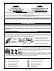
❑ (1) Fuselage
❑ (1) Wing with Ailerons
❑ (1) Horizontal Stabilizer with Elevator
❑ (1) Vertical Stabilizer with Rudder
❑ (2) Landing Gear Wires
❑ (1) Tail Skid
❑ (2) Wheels
❑ (2) Nylon Landing Gear Straps
❑ (2) Nylon Axle Spacers
❑ (2) Wheel Collars
❑ (2) M3 x 5mm Machine Screws
❑ (4) M2 x 10mm Wood Screws
❑ (1) 5-1/2" (140mm) Threaded Wire with Z-Bend
❑ (1) 4-1/8" (105mm) Threaded Wire with Z-Bend
❑ (2) 2-3/4" (70mm) Threaded Wires with Z-Bends
❑ (4) Nylon Control Horns with Backplates
❑ (4) Nylon Clevises
❑ (8) M2 x 10mm Machine Screws
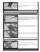
KIT CONTENTS
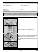
AIRFRAME ASSEMBLIES
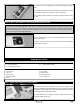
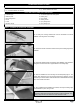
LANDING GEAR ASSEMBLY
CONTROL SYSTEM ASSEMBLIES
TOOLS AND SUPPLIES REQUIRED