
Specifications

Page 19
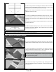
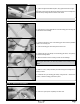
❑ Using a clean cloth, wipe the airframe down completely to remove any dust, debris and oil.
❑ Cut out each of the decals and apply them using the box cover photos for reference. If any air bubbles form under the decals
when you apply them, use a T-Pin to puncture the bubble and release the trapped air, then press the decal down.
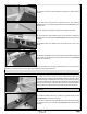
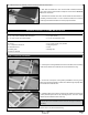
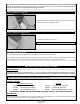
❑ Mount the battery to the fuselage oor, directly behind the motor, using
the strip of hook and loop material included.
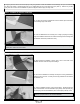
❑ Drill a 5/64" (2mm) diameter hole through the bottom of the fuselage for the antenna to exit, then run the antenna out and along
the bottom of the fuselage. Use pieces of clear tape to secure it into place along the length of the fuselage. Do not cut the antenna
shorter. Allow the excess to hang beyond the back of the fuselage.
STEP 3: INSTALLING THE BATTERY
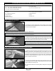
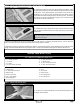
STEP 4: INSTALLING THE PROPELLER
❑ Install your propeller onto the motor.
IMPORTANT Make sure to tighten the propeller nut rmly.
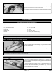
Ailerons: 5/8" (16mm) Up and Down
Elevator: 1/2" (13mm) Up and Down
Rudder: 1/2" (13mm) Right and Left
Test Flying and Sport Flying
3D Flying
BALANCE POINT:
THE CONTROL THROWS ARE MEASURED FROM THE WIDEST POINT OF THE CONTROL SURFACES
Ailerons: 1-1/2" (38mm) Up and Down
Elevator: 1" (25mm) Up and Down
STEP 5: APPLYING THE DECALS
BALANCE POINT AND CONTROL THROWS
WARNING For test ying and general sport ying, we suggest you balance the airplane at the C/G recommended above.
Experienced pilots can experiment with the C/G range as far back as 5" (127mm).
CONTROL THROWS:
EXPONENTIAL:
For all control surfaces, we recommend 15% to 25% exponential on high rates (3D Flying). For more information about exponential
and how to program it, please refer to your radio system's user's guide.