
Specifications

Page 16
❑ 5 Minute Epoxy
❑ # 1 Phillips Head Screwdriver
❑ Modeling Knife
❑ Electric or Hand Drill
❑ 1/16" (1.6mm) Drill Bit
❑ Straight Edge Ruler
❑ (2) Landing Gear Wires
❑ (1) Tail Skid
❑ (2) Wheels
❑ (2) Nylon Landing Gear Straps
❑ (2) Nylon Axle Spacers
❑ (2) Wheel Collars
❑ (2) M3 x 5mm Machine Screws
❑ (4) M2 x 10mm Wood Screws
❑ Pencil
❑ Paper Towels
❑ Rubbing Alcohol
❑ Epoxy Mixing Sticks
❑ Epoxy Mixing Cups
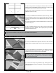
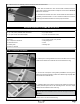
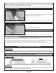
❑ Cut away the covering material from over the tail skid mounting hole in
the bottom of the fuselage.
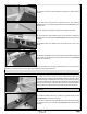
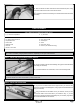
❑ Double-check that both the servo horn and the aileron are still centered. If necessary, thread the clevis in or out to center the
aileron, then move the aileron up and down several times to ensure proper movement.
❑ Repeat the previous procedures to install the second aileron control linkage assembly. When adjusting the second aileron control
linkage, make sure that both ailerons are even with each other. You don’t want one aileron to be higher or lower than the other one.
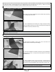
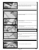
❑ Position and install one control horn onto the bottom of one aileron, using
the same techniques that you used to install both the elevator and the rudder
control horns. When aligned properly, the centerline of the control horn
should be 4-1/2" (114mm) out from the inside edge of the aileron and the
clevis attachment holes should be lined up over the hinge line. The base of
the control horn should be parallel to the hinge line, too, so that the control
horn will line up with the pushrod wire.
IMPORTANT Don't forget to apply a couple of drops of thin C/A to the pilot holes.
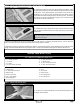
STEP 2: INSTALLING THE AILERON CONTROL LINKAGE ASSEMBLIES
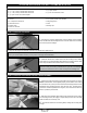
❑ Install the servo arm, pushrod wire and clevis, using the same techniques
that you used to install the elevator and rudder servo arms, pushrod wires
and clevises.
IMPORTANT The servo arm should point toward the middle of the
wing. Don't forget to install the servo horn retaining screw to secure the
servo horn to the servo.
LANDING GEAR INSTALLATION
YOU'LL NEED THE FOLLOWING PARTS FROM THE KIT:
YOU'LL NEED THE FOLLOWING TOOLS AND SUPPLIES:
STEP 1: INSTALLING THE TAIL SKID