
Specifications

Page 15
❑ Thin C/A
❑ # 1 Phillips Head Screwdriver
❑ Needle Nose Pliers
❑ Modeling Knife
❑ Electric or Hand Drill
❑ (2) 2-3/4" (70mm) Threaded Wires with Z-Bends
❑ (2) Nylon Control Horns with Backplates
❑ (2) Nylon Clevises
❑ (4) M2 x 10mm Machine Screws
❑ 1/16" (1.6mm) & 5/64" (2mm) Drill Bits
❑ Straight Edge Ruler
❑ Pencil
❑ Masking Tape
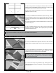
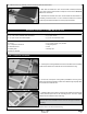
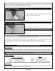
❑ Cut away the covering material from over the two aileron servo mounting
holes and the aileron servo lead exit hole in the bottom of the wing.
❑ Tie the end of the piece of string that's preinstalled in the wing to the
aileron servo lead and use that to pull the servo lead through the paper tube
and out the servo lead exit hole.
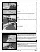
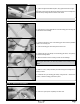
❑ Repeat the previous procedures to install the second aileron servo in the other half of the wing.
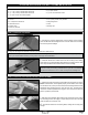
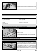
❑ With both the rudder servo horn and the rudder centered, thread one
nylon clevis onto the pushrod wire and snap the clevis into the outermost
hole in the control horn.
❑ Double-check that both servo horn and the rudder are still centered. If
necessary, thread the clevis in or out to center the rudder, then move the
rudder right and left several times to ensure proper movement.
❑ Install the servo horn retaining screw to secure the servo horn to the servo.
AILERON CONTROL SYSTEMS INSTALLATION
YOU'LL NEED THE FOLLOWING PARTS FROM THE KIT:
YOU'LL NEED THE FOLLOWING TOOLS AND SUPPLIES:
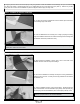
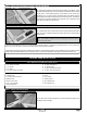
❑ Install the aileron servo into the mounting hole, making sure to drill 1/16"
(1.6mm) diameter pilot holes for the mounting screws. The servo output
shaft should be toward the back of the wing.
IMPORTANT Depending on the length of your servo lead, you may
need to add a servo extension lead to reach out through the bottom of
the wing.