
Specifications

Page 14
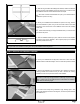
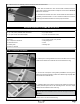
❑ Center the servo, then install the servo horn onto the servo, making sure
that the servo horn is centered and pointing down toward the bottom of the
fuselage.
❑ Install the servo horn retaining screw to secure the servo horn to the
servo.
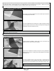
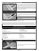
❑ With both the elevator servo horn and the elevator centered, thread one
nylon clevis onto the pushrod wire and snap the clevis into the outermost
hole in the control horn.
❑ Double-check that both the servo horn and the elevator are still centered. If necessary, thread the clevis in or out to center the
elevator, then move the elevator up and down several times to ensure proper movement.
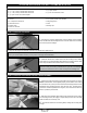
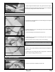
❑ Install the Z-Bend in the 5-1/2" (140mm) long pushrod wire into the
outermost hole in a "4-point" servo horn.
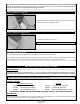
❑ Center the rudder servo, then install the servo horn onto the servo, making
sure that the servo horn is centered and pointing out toward the side of the
fuselage.
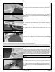
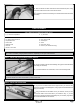
❑ Position and install one control horn onto the left side of the rudder, using
the same techniques that you used to install the elevator control horn. When
positioned properly, the centerline of the control horn should be 2-1/8" (54mm)
up from the bottom of the rudder and the clevis attachment holes should be
lined up over the hinge line. The base of the control horn should be parallel to
the hinge line, too, so that the control horn will line up with the pushrod wire.
IMPORTANT Don't forget to apply a couple of drops of thin C/A to the
pilot holes.
❑ Install the control horn and backplate, using two M2 x 10mm machine
screws.
❑ Cut away all but one arm from a "4-point" servo horn, then install the
Z-Bend in the 4-1/8" (105mm) long pushrod wire into the outermost hole in
the servo arm.
☞
You may need to enlarge the hole to t the diameter of the wire.
STEP 3: INSTALLING THE RUDDER CONTROL LINKAGE ASSEMBLY