
Specifications

Page 10
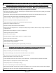
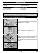
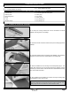
❑ Measure and draw a centerline mark on the top of the trailing edge of the
stabilizer.
❑ Extend the centerline mark across the top of the stabilizer, using a builder’s
triangle to ensure that the line is perpendicular to the trailing edge.
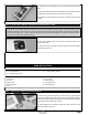
❑ Slide the stabilizer into the mounting slot and temporarily align it. The
trailing edge should be even with the back edge of the fuselage, and the
centerline you drew should be centered within the vertical stabilizer mounting
slot, when viewed from above.
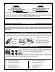
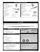
❑ 5 Minute Epoxy
❑ Modeling Knife
❑ Straight Edge Ruler
❑ Pencil
❑ T-Pins
❑ Builder's Triangle
❑ (1) Horizontal Stabilizer with Elevator
❑ (1) Vertical Stabilizer with Rudder
❑ 220 Grit Sandpaper with Sanding Block
❑ Masking Tape
❑ Paper Towels
❑ Rubbing Alcohol
❑ Epoxy Mixing Sticks
❑ Epoxy Mixing Cups
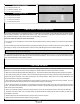
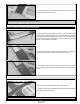
❑ Cut away the covering material from over the horizontal and vertical
stabilizer mounting slots in the fuselage.
STABILIZER INSTALLATION
YOU'LL NEED THE FOLLOWING PARTS FROM THE KIT:
YOU'LL NEED THE FOLLOWING TOOLS AND SUPPLIES:
STEP 1: ALIGNING THE HORIZONTAL STABILIZER
❑ When satised that the stabilizer is centered, hold only the trailing edge
of the stabilizer in place, using a T-Pin.
IMPORTANT The front of the stabilizer should be able to pivot slightly
from side to side and the back should stay rmly in place and aligned. The
trailing edge should not be allowed to move from side to side.