
Specifications


Page 38
C/G AND BALANCING
BALANCE POINT (C/G):
l
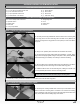
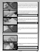
q Turn the aircraft upside down, place your ngers on the wing at the balance point, then carefully lift the aircraft. If the nose of the
aircraft drops, the aircraft is nose heavy. To correct this, move the battery and/or receiver back far enough to bring the aircraft into
balance. If the tail of the aircraft drops, the aircraft is tail heavy. To correct this, move the battery and/or receiver forward far enough to
bring the aircraft into balance.
IMPORTANT It is critical that your aircraft be balanced correctly. Incorrectly balancing your aircraft can cause your aircraft to lose
control and crash!
+
Once you have own and become familiar with the ight characteristics of the aircraft, the C/G can be moved fore or aft up to 1/2"
(13mm) in either direction to change the ight performance. Moving the C/G back will cause the aircraft to be more responsive, but less
stable. Moving the C/G forward will cause the aircraft to be more stable, but less responsive.
YOU CAN MOvE ThE C/G BACk IN SMALL INCREMENTS UNTIL YOU ARE SATISfIEd WITh ThE fLIGhT
ChARACTERISTICS, hOWEvER, MOvING ThE C/G TOO fAR BACk COULd RESULT IN LOSS Of CONTROL.
IMPORTANT Balance the aircraft with the fuel tank empty.
LATERAL BALANCING
Lateral balancing will make the aircraft track straighter in the air and make it easier to trim the control surfaces for optimum ight
performance. It is strongly recommended.
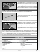
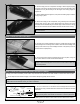
q Turn the aircraft upside down and tie one length of heavy string to the propeller shaft and loop a second length of heavy string
around the tail wheel.
q With someone helping you, carefully lift the aircraft up by the two pieces of heavy string. Watch how the wing reacts. If one side of
the wing drops, that side is heavier than the other. To correct this, stick a small piece of self-adhesive lead weight to the bottom of the
lighter side of the wing (the one that doesn't drop). For best mechanical advantage, place the weight as close to the wing tip as possible,
but make sure to apply the lead weight to a solid portion of the wing structure so that it can't rip off during ight.
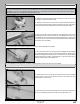
q Repeat the procedure a couple of more times to double-check your ndings. When done properly the wing should stay level when
you lift the aircraft.
CONTROL THROWS
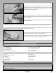
Ailerons: 3/4" (19mm) Up / Down
Rudder: 1" (25mm) Right / Left
TEST FLYING
THE CONTROL THROWS ARE MEASURED FROM THE
WIDEST POINT OF THE CONTROL SURFACES.
IMPORTANT As you increase the control throws, the aircraft will become more sensitive and react much more quickly to control
inputs. We do not suggest increasing the control throws unless you are a procient yer. We also recommend using Exponential as
described on the next page. Higher control throws will cause the airplane to be extremely control sensitive and result in a possible
crash if you are not careful.
We recommend initially setting up the aircraft using the Test Flying control throws. These control throws are suggested for initial test
ying because they will allow the aircraft to y smoother and make it easier to control. For sport ying and aerobatics, increase the
control throws by 1/8" (3mm) at a time until you're satised with the result, but only AFTER you've become familiar with the ight
characteristics of the aircraft using the Test Flying control throws.
DON'T FORGET TO INSTALL THE PIECES OF HEAT-
SHRINK TUBING OVER THE CLEVISES AS DESCRIBED IN
THE CONTROL SYSTEMS INSTALLATION SECTIONS.
Ailerons: 45º Up / Down
Rudder: 60º Right / Left
3D FLYING