
Specifications


Page 34
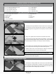
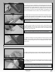
q Remove the cowl from the fuselage, then measure forward from each of
the lines that you drew to mark the back edge of the cowl to the centre of the
predrilled hole in each of the cowl mounting blocks. Make a note of these
measurements for the next procedure.
q Measure the resulting distances forward from the back edge of the cowl
and draw intersecting lines onto the cowl over the lines that you extended onto
the cowl previously.
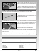
q Carefully drill 1/8" (3mm) diameter holes through the cowl at each of the
ve intersecting lines.
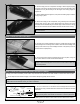
q Mark and cut out the areas of the cowl necessary to give you access to your engine's high and low speed needle valves, glow plug
and choke lever (if featured). You should also install a fuel valve into a convenient location on the bottom or side of the cowl.
+
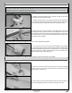
Many engines will require the use of a needle valve extension to access the high speed needle valve. We suggest making one from
scrap 1.5mm diameter wire of sufcient length for easy access outside of the cowl.
q Connect the fuel lines from the fuel tank to your engine's carburetor, mufer
and fuel valve, then slide the cowl into position and realign it.
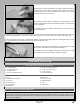
q Install the cowl onto the fuselage, using ve M3 x 10mm machine screws
and ve M3 at washers, then install your propeller and spinner.
q (1) Stranded Cable
q (7) Aluminium Brackets
q (8) Metal Eyelets
q (3) M3 x 25mm Machine Screws
q (8) M3 x 10mm Machine Screws
q (1) M3 x 12mm Wood Screw
q (11) M3 Lock Nuts
q (23) M3 Flat Washers
FLYING WIRES INSTALLATION
YOU'LL NEED THE FOLLOWING PARTS FROM THE KIT:
YOU'LL NEED THE FOLLOWING TOOLS AND SUPPLIES:
q Thin C/A
q # 2 Phillips Head Screwdriver
q Wire Cutters
q Adjustable Wrench
q Needle Nose Pliers
q Modeling Knife
q Electric Drill
q 5/64" (2mm) Drill Bit
q Straight Edge Ruler
q Pencil
q Airplane Stand
STEP 1: INSTALLING THE MOUNTING BRACKETS
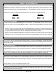
IMPORTANT Three different styles of mounting brackets are included. The mounting bracket with three holes in it is installed on
the bottom of the fuselage. The two mounting brackets that are bent at a shallow angle are installed on the bottom of the horizontal
stabiliser and the four mounting brackets that are bent at a steeper angle are installed on the top of the horizontal stabiliser and the
sides of the vertical stabiliser.