
Specifications


Page 32
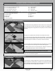
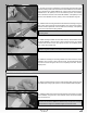
q Slide one M3 at washer onto one M3 x 50mm machine screw, then push
the machine screw up through the control horn mounting hole. Slide a second
M3 at washer onto the machine screw, then thread one M3 lock nut onto the
machine screw and tighten it rmly.
q Thread one nylon adjustable control horn onto the machine screw until the top
of the control horn is 1/8" (3mm) below the end of the machine screw, then repeat
the previous procedures to install the aileron control horn onto the other aileron.
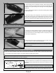
STEP 3: INSTALLING THE AILERON CONTROL LINKAGES
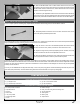
q Use a couple of pieces of masking tape, taped between one aileron and the wing panel, to hold the aileron centred.
q Temporarily thread one M3 hex nut and one 3mm clevis onto each end of
one 2-3/8" (60mm) threaded pushrod wire.
q Snap the clevis on one end of the threaded pushrod wire into the hole in
the servo arm that is 3/4" (19mm) out from the centre of the servo horn.
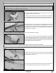
q Adjust the length of the pushrod by adjusting the two clevises, then snap
the second clevis into the hole in the adjustable control horn.
q With both the aileron and the servo horn centred, rmly tighten the two hex
nuts up against the clevises to lock the pushrod wire into place.
q Centre the aileron servo and install a servo horn onto the servo, making sure that the servo arm is centred and points toward the
wing tip. Install the servo horn retaining screw to secure the servo horn to the servo.
q Repeat the previous procedures to assemble and install the second aileron control linkage. Remove the masking tape from the
ailerons and double-check that both servo horns and both ailerons are still centred. If the ailerons are not centred, readjust the clevises
until they are, then move the ailerons up and down several times to ensure that the control linkages do not bind. They should operate
smoothly in both directions.
q
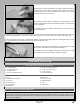
Once you are satised with the alignment and setup, cut four 1/8" (3mm) long pieces of heat-shrink tubing and slide one piece over
each clevis (see photo above). The heat-shrink tubing will ensure that the clevises do not open up during ight.
q (1) Fiberglass Cowl
q (2) Clear Mock-Up Cowl Halves
q (5) M3 x 10mm Machine Screws
q (5) M3 Flat Washers
COWL INSTALLATION
YOU'LL NEED THE FOLLOWING PARTS FROM THE KIT:
YOU'LL NEED THE FOLLOWING TOOLS AND SUPPLIES:
q # 2 Phillips Head Screwdriver
q Adjustable Wrench
q Scissors
q Electric Drill
q 1/8" (3mm) Drill Bit
q Straight Edge Ruler
q Pencil
q Builder's Triangle
q Rotary Tool with Cutting Disc and Sanding Drum
q 220 Grit Sandpaper
q Sanding Block
q Masking Tape
q Airplane Stand