
Specifications


Page 31
q (2) 2-3/8" (60mm) Threaded Pushrod Wires
q (2) M3 x 50mm Machine Screws
q (2) Nylon Adjustable Control Horns
q (4) Metal Clevises - 3mm Thread
q (4) M3 Flat Washers
q (2) M3 Lock Nuts
q (4) M3 Hex Nuts
q (1) Heat-Shrink Tubing
AILERON CONTROL SYSTEM INSTALLATION
YOU'LL NEED THE FOLLOWING PARTS FROM THE KIT:
YOU'LL NEED THE FOLLOWING TOOLS AND SUPPLIES:
q # 1 and # 2 Phillips Head Screwdrivers
q Adjustable Wrench
q Modeling Knife
q Electric Drill
q 1/16" (1.6mm) Drill Bit
q Straight Edge Ruler
q Pencil
q Masking Tape
q Heat Gun
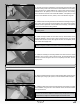
STEP 1: INSTALLING THE ELEVATOR SERVOS
q Cut away the covering material from over the aileron servo mounting hole
in one wing panel. The servo mounting hole is located 10-1/4" (260mm) out
from the root edge of the wing panel and 2-3/4" (70mm) in front of the aileron
hinge line.
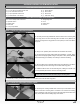
q Plug one 12" (305mm) servo extension onto the aileron servo lead.
q To prevent the plugs from pulling apart during assembly, or worse, during
ight, secure the plugs together, using a short piece of 3/8" (10mm) diameter
heat-shrink tubing (not included). Use a heat gun to shrink the tubing.
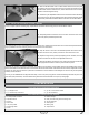
IMPORTANT Note the orientation of the servo. When installed, the servo
output shaft should be toward the leading edge of the wing panel.
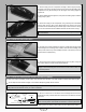
q Run the aileron servo extension lead through the guide tube in the aileron
servo mounting hole and out through the root end of the wing panel.
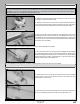
q Install the aileron servo into the mounting hole, making sure to drill 1/16"
(1.6mm) diameter pilot holes for the servo mounting screws.
q Repeat the previous procedures to install the second aileron servo into the other wing panel.
STEP 2: INSTALLING THE AILERON CONTROL HORNS
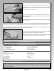
q Cut away the covering material from over the top and the bottom of the
aileron control horn mounting hole in one aileron. The control horn mounting
hole is located 8-11/16" (221mm) out from the inside edge of the aileron and
3/8" (10mm) back from the leading edge of the aileron.