
Specifications

Page 28
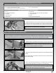
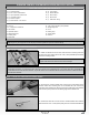
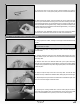
IMPORTANT It's important that both elevator halves track evenly together throughout the entire range of deection. If one elevator
half moves more than the other, this will cause the aircraft to roll when it pitches up or down during ight.
Looking from the back of the fuselage at the trailing edge of both elevator halves, slowly move the elevator halves up and down
several times (using the transmitter control stick) to ensure that both elevator halves track evenly together throughout the entire
range of deection.
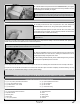
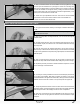
If the elevator halves do not track together (i.e., one elevator half moves more than the other though the range of deection), you will
need to thread one or both of the adjustable control horns up or down slightly until both elevator halves track evenly. Depending on your
radio control system, and if you've plugged each elevator servo separately into your receiver, you may be able to make adjustments
to each elevator half separately via your transmitter. Please refer to your radio control system's User's Guide for more information.
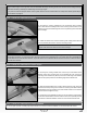
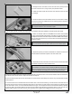
q Once you are satised with the alignment and setup, cut four 1/8" (3mm) long pieces of heat-shrink tubing and slide one piece over
each clevis (see photos on previous page). The heat-shrink tubing will ensure that the clevises do not open up during ight.
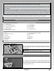
q (1) Stranded Cable
q (1) M3 x 70mm Threaded Rod
q (2) Nylon Adjustable Control Horns
q (2) Threaded Couplers
q (2) Z-Bend Couplers
q (2) Metal Clevises - 2mm Thread
q (4) Crimp Collets
q (2) M3 Flat Washers
q (2) M3 Lock Nuts
q (2) M2 Hex Nuts
q (1) Heat-Shrink Tubing
RUDDER CONTROL SYSTEM INSTALLATION
YOU'LL NEED THE FOLLOWING PARTS FROM THE KIT:
YOU'LL NEED THE FOLLOWING TOOLS AND SUPPLIES:
q Thin C/A
q # 1 Phillips Head Screwdriver
q Wire Cutters
q Adjustable Wrench
q Needle Nose Pliers
q Modeling Knife
q Electric Drill
q 1/16" (1.6mm) and 5/64" (2mm) Drill Bits
q Straight Edge Ruler
q Pencil
q Masking Tape
q Airplane Stand
q Heat Gun
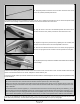
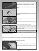
STEP 1: INSTALLING THE RUDDER SERVO
q Install the rudder servo into the centre servo mounting hole in the plywood
servo tray, making sure to drill 1/16" (1.6mm) diameter pilot holes for the servo
mounting screws.
IMPORTANT Note the orientation of the servo. When installed, the servo
output shaft should be toward the front of the fuselage.
STEP 2: INSTALLING THE RUDDER CONTROL HORN
q Cut away the covering material from over both sides of the rudder control
horn mounting hole in the rudder. The control horn mounting hole is located
6-1/2" (165mm) up from the bottom of the rudder and 3/8" (10mm) back from
the leading edge of the rudder.