
Specifications

Page 26
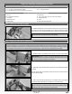
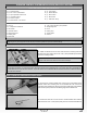
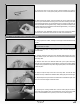
q Slide one M3 at washer onto the threaded rod and up against the lock
nut, then push the threaded rod up through the control horn mounting hole.
Slide a second M3 at washer onto the threaded rod, then thread one M3 lock
nut onto the threaded rod and tighten it rmly, making sure that the threaded
rod is centred. Both ends of the threaded rod should be approximately 1-1/4"
(32mm) from the surface of the elevator half.
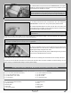
q Thread one nylon adjustable control horn onto each end of the threaded
rod until both control horns are ush with the ends of the threaded rod.
q Repeat the previous procedures to install the elevator control horn onto the other elevator half.
STEP 3: INSTALLING THE ELEVATOR PULL-PULL CABLES
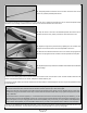
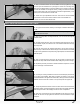
q Carefully thread the same end of the stranded cable through the hole in
one threaded coupler, then slide the end of the stranded cable back through
the crimp collet.
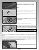
q Hold the short end of the stranded cable with a pair of pliers and rmly
slide the crimp collet forward so that the ange covers the end of the threaded
coupler. Firmly squeeze the crimp collet, using a pair of pliers, to lock the stranded
cable into place.
q Apply a couple of drops of thin C/A to the crimp collet. The C/A will 'wick'
between the crimp collet and the stranded cable, making the joint even stronger.
q Repeat the previous procedures to install a threaded coupler onto one end
of the other length of stranded cable.
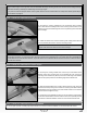
q Using a pair of wire cutters, carefully cut one length of stranded cable exactly
in half.
q Slide one crimp collet, non-anged side rst, over one end of one length of
stranded cable.
PRO TIP If the ends of the cable begin to unravel, use your ngers to twist
the ends back into shape.
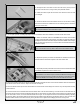
q Cut away the covering material from over the two elevator pull-pull exit slots
in one side of the fuselage. Both slots are located 2" (50mm) in front of the
horizontal stabiliser. The upper slot is located 5/8" (16mm) up from the horizontal
stabiliser and the lower slot is located 1-3/4" (45mm) below the upper slot.
q Temporarily thread one M2 hex nut and one 2mm clevis onto each of the two
threaded couplers, then feed the plain end of each of the two lengths of stranded
cable through the slots in the fuselage and into the servo compartment.
q
Snap each clevis into the hole in the adjustable control horns, then rmly
tighten the two hex nuts up against the clevises to lock the threaded coupler
into place.