
Specifications

Page 24
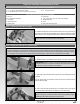
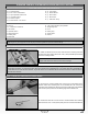
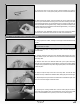
q Temporarily thread one M3 hex nut and one 3mm clevis onto each end of
one 8-1/2" (216mm) threaded pushrod wire.
q Snap the clevis on one end of the threaded pushrod wire into the hole in
the servo arm that is 3/4" (19mm) out from the centre of the servo horn.
q Adjust the length of the pushrod wire by adjusting the two clevises, then
snap the second clevis into the hole in the adjustable control horn.
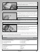
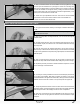
q With both the elevator half and the servo horn centred, rmly tighten the
two hex nuts up against the two clevises to lock the pushrod wire into place.
q Repeat the previous procedures to assemble and install the second elevator
control linkage.
q Remove the masking tape from the elevator halves and double-check that both servo horns and both elevator halves are still
centred. If the elevator halves are not centred, readjust the clevises until they are.
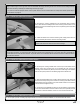
q
Move the elevator halves up and down several times to ensure that the control linkages do not bind. They should operate smoothly
in both directions.
IMPORTANT It's important that both elevator halves track evenly together throughout the entire range of deection. If one elevator
half moves more than the other, this will cause the aircraft to roll when it pitches up or down during ight.
Looking from the back of the fuselage at the trailing edge of both elevator halves, slowly move the elevator halves up and down
several times (using the transmitter control stick) to ensure that both elevator halves track evenly together throughout the entire
range of deection.
If the elevator halves do not track together (i.e., one elevator half moves more than the other though the range of deection), you will
need to thread one or both of the adjustable control horns up or down slightly until both elevator halves track evenly. Depending on your
radio control system, and if you've plugged each elevator servo separately into your receiver, you may be able to make adjustments
to each elevator half separately via your transmitter. Please refer to your radio control system's User's Guide for more information.
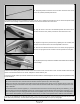
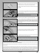
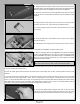
q Centre the elevator servo and install a servo horn onto the servo, making sure that the servo arm is centred and points toward
the bottom of the fuselage. Install the servo horn retaining screw to secure the servo horn to the servo.
q Once you are satised with the alignment and setup, cut four 1/8" (3mm) long pieces of heat-shrink tubing and slide one piece over
each clevis (see photo above). The heat-shrink tubing will ensure that the clevises do not open up during ight.