
Specifications

Page 23
IMPORTANT This section details the installation of the push-pull rear mounted elevator control system. Use this option if you are
using a heavier engine on the high end of the recommended size range. Mounting the servos in the back of the fuselage will help
balance the aircraft by off-setting the added weight of the larger engine.
If you prefer to install the pull-pull elevator control system with the servos mounted below the cockpit deck instead, please skip to
the next section on page 25.
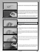
STEP 1: INSTALLING THE ELEVATOR SERVOS
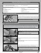
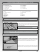
q Cut away the covering material from over the elevator servo mounting
hole in each side of the fuselage. Each servo mounting hole is located 14-1/4"
(362mm) in front of the rudder hinge line and 2-1/2" (64mm) up from the bottom
of the fuselage.
q Install one elevator servo into each mounting hole, making sure to drill 1/16"
(1.6mm) diameter pilot holes for the servo mounting screws.
IMPORTANT Note the orientation of the servos. When installed, both servo
output shafts should be toward the back of the fuselage.
IMPORTANT Both elevator servos and control linkages are mirrored to ensure the highest degree of accuracy between the right
and left sides, therefore, you will need to either plug each elevator servo separately into your receiver and use a transmitter mix
to make both servos move the same direction, or you will need to use a Y-Harness with an electronic reverser to make both servos
move the same direction.
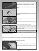
STEP 2: INSTALLING THE ELEVATOR CONTROL HORNS
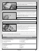
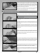
q Cut away the covering material from over the top and the bottom of the
elevator control horn mounting hole in one elevator half. The control horn
mounting hole is located 7/8" (22mm) out from the inside edge of the elevator
half and 3/8" (10mm) back from the leading edge of the elevator half.
q Slide one M3 at washer onto one M3 x 40mm machine screw, then push
the machine screw up through the control horn mounting hole. Slide a second
M3 at washer onto the machine screw, then thread one M3 lock nut onto the
machine screw and tighten it rmly.
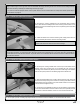
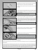
q Thread one nylon adjustable control horn onto the machine screw until the
control horn is ush with the end of the machine screw, then repeat the previous
procedures to install the elevator control horn onto the other elevator half.
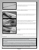
STEP 3: INSTALLING THE ELEVATOR CONTROL LINKAGES
q Use a couple of pieces of masking tape, taped between one elevator half and the stabiliser, to hold the elevator half centred.