
Specifications

Page 22
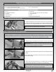
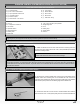
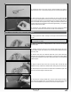
q Install the Z-Bend in the pushrod wire into the outermost hole in your engine's
throttle arm, slide the pushrod wire through the hole that you drilled in the front
of the fuselage, then reinstall your engine.
IMPORTANT Depending on the engine you're using, it might be necessary
to make a shallow bend in the pushrod wire to achieve perfect alignment, or to
prevent the pushrod wire from hitting the side of the engine mounting box.
STEP 3: INSTALLING THE ADJUSTABLE PUSHROD CONNECTOR
IMPORTANT To prevent the nut from loosening during ight, apply a drop
of thin C/A to it.
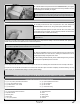
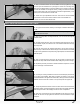
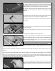
q Cut away all but one arm from a '4-point' servo horn, then enlarge the
outermost hole in the servo arm, using a 5/64" (2mm) diameter drill bit.
q Install the adjustable pushrod connector onto the servo arm, making sure
not to tighten the nut too tightly. You don't want the pushrod connector loose,
but it should be able to rotate without binding.
q Connect your radio control system, check that the throttle servo output shaft is rotating in the correct direction, then position the
throttle control stick and the throttle trim lever to their lowest positions.
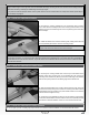
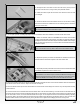
q Slide the adjustable pushrod connector assembly onto the pushrod wire,
then install the servo horn onto the servo, making sure that the servo horn is
angled approximately 30 degrees from centre.
q While holding the carburetor fully closed, install and tighten the grub screw
in the top of the adjustable pushrod connector.
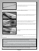
q Cut away the excess pushrod wire, then install and tighten the servo horn retaining screw to hold the servo horn securely to the servo.
q Open and close the throttle several times to ensure that the carburetor opens and closes completely and without binding. You may
need to adjust your transmitter EPA settings to achieve perfect settings.
IMPORTANT Depending on the length of the servo arm that you're using, you may need to make a bend in the pushrod wire to
line up with the adjustable pushrod connector in the next procedure.
q (2) 8-1/2" (216mm) Threaded Pushrod Wires
q (2) M3 x 40mm Machine Screws
q (4) Metal Clevises - 3mm Thread
q (4) M3 Hex Nuts
q (2) Nylon Adjustable Control Horns
q (4) M3 Flat Washers
q (2) M3 Lock Nuts
q (1) Heat-Shrink Tubing
ELEVATOR CONTROL SYSTEM INSTALLATION (PUSH-PULL OPTION)
YOU'LL NEED THE FOLLOWING PARTS FROM THE KIT:
YOU'LL NEED THE FOLLOWING TOOLS AND SUPPLIES:
q # 1 and # 2 Phillips Head Screwdrivers
q Adjustable Wrench
q Modeling Knife
q Electric Drill
q 1/16" (1.6mm) Drill Bit
q Straight Edge Ruler
q Pencil
q Masking Tape
q Airplane Stand
q Heat Gun