
Specifications

Page 18
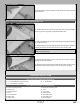
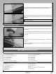
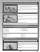
q Install one M3 blind nut into the wheel pant, then carefully apply a bead of
thick C/A around the blind nut for extra security.
PRO TIP Thread one M3 x 10mm machine screw and one at washer
into the blind nut, then tighten the machine screw to draw the blind nut
into place.
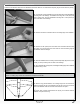
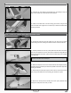
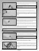
q Slide the wheel pant back into position and secure it to the landing gear
bracket, using one M3 x 10mm machine screw.
q Loosen the grub screws in the wheel collars, centre the wheel between the
sides of the wheel pant opening, then retighten the grub screws and double-
check that the wheel spins freely.
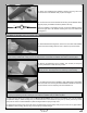
q Repeat the previous procedures to install the second wheel and wheel pant assembly. When installing the second wheel pant, make
sure that it's parallel to the rst wheel pant.
q 3mm Hex Wrench
q 7mm Nut Driver
q (2) Aluminium Engine Mounting Beams
q (4) M4 x 35mm Socket-Cap Screws
q (4) M4 x 25mm Socket-Cap Screws
q (4) M4 Lock Nuts
q (4) M4 Blind Nuts
q (4) M4 Split Washers
q (12) M4 Flat Washers
q Straight Edge Ruler
ENGINE INSTALLATION
YOU'LL NEED THE FOLLOWING PARTS FROM THE KIT:
YOU'LL NEED THE FOLLOWING TOOLS AND SUPPLIES:
STEP 1: INSTALLING THE ENGINE MOUNTING BEAMS
IMPORTANT The following procedures outline the installation of a four-stroke engine. If you are installing a two-stroke engine, the
installation procedures are the same. The Magnum XL 1.20RFS engine is shown.
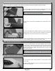
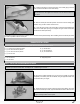
q Remove the mufer assembly from your engine, then install your spinner
backplate (not included) onto the crankshaft, using the propeller washer and
nut included with your engine.
q Temporarily mount your engine onto the engine mounting beams, using four
M4 x 35mm socket-cap screws, eight M4 at washers and four M4 lock nuts.
PRO TIP Mount the engine as far forward as possible to ensure that the
engine mounting beams remain square.