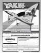
Optimized for Precision 3D aerobatics, the Model Tech Yak 54 ARF has enlarged and modified control surfaces to enhance control response at low-airspeed and high-alpha. Wrung out by Model Tech test pilots in months of testing, the Yak 54 ARF has already proven to be a stunning performer. You'll find this Yak 54 ARF is perfectly 3D capable when matched with a YS 110 or Magnum 120 four-stroke and is insanely overpowered with an engine such as the Mark/Moki 1.35 two-stroke.
TABLE OF CONTENTS INTRODUCTION........................................................................................................ 2 THROTTLE CONTROL SYSTEM INSTALLATION................................................... 21 SAFETY WARNING................................................................................................... 2 ELEVATOR CONTROL SYSTEM INSTALLATION (PUSH-PULL OPTION)............. 22 OUR GUARANTEE...............................................................................
OUR RECOMMENDATIONS This section describes our recommendations to help you in deciding which types of accessories to purchase for your new aircraft. Please read through this entire section very carefully. We have provided you with recommendations that, if followed, will result in a great flying aircraft. Failure to follow our recommendations may result in a poor flying aircraft. WHAT glow ENGINE SHOULD i USE? The Yak 54 ARF can be flown using either a 1.00 to 1.35 size two-stroke engine or a 1.20 to 1.
TOOLS AND SUPPLIES REQUIRED q 5 Minute and 30 Minute Epoxy q Straight Edge Ruler q Thin and Thick Cyanoacrylate (C/A) q Pencil q C/A Debonder q Builder's Triangle q Thread Locking Compound q 220 Grit Sandpaper q Formula 560 Canopy Glue q Sanding Block q Silicon Sealant q Rotary Tool with Cutting Disc and Sanding Drum q # 1 and # 2 Phillips Head Screwdrivers q Masking Tape q 2.5mm and 3mm Hex Wrenches q Airplane Stand q 5.
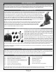
KIT CONTENTS Before you begin assembly, group the parts as we list them below. This will ensure that you have all of the parts before you begin assembly and it will also help you become familiar with each part. If you find any parts missing or damaged, please contact your local Model Tech dealer directly, using the separate Customer service sheet included with your kit.
ELEVATOR CONTROL SYSTEM (PUSH-PULL OPTION) q (2) 8-1/2" (216mm) Threaded Pushrod Wires q (2) M3 x 40mm Machine Screws q (4) Metal Clevises - 3mm Thread q (4) M3 Hex Nuts RUDDER CONTROL SYSTEM q (1) Stranded Cable q (1) M3 x 70mm Threaded Rod q (2) Nylon Adjustable Control Horns q (2) Threaded Couplers q (2) Z-Bend Couplers q (2) Metal Clevises - 2mm Thread q (4) Crimp Collets q (2) M3 Flat Washers q (2) M3 Lock Nuts q (2) M2 Hex Nuts q (3) Pinned Hinges AILERON CONTROL SYSTEM q (2) 2-3/8" (60mm) Threaded
FUEL TANK ASSEMBLY q (1) 500cc Fuel Tank q (3) Aluminium Tubes q (1) Rubber Stopper q (1) Metal Plate - Small q (1) Metal Plate - Large q (1) Fuel Pick-up (Clunk) q (1) Silicone Fuel Tubing q (1) Metal Support Ring q (1) M3 x 20mm Machine Screw WING MOUNTING ASSEMBLY q (1) Wing Joiner Tube q (4) Knurled Aluminium Posts q (4) Rubber O-Rings q (4) M6 Flat Washers q (4) Retaining Clips MISCELLANEOUS PARTS q (2) Clear Mock-Up Cowl Halves (Not Pictured) q (2) M3 x 16mm Machine Screws q (5) M3 x 10mm Machine Sc
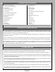
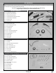
WING ASSEMBLY You'll Need the following parts FROM THE KIT: q (1) Right Wing Panel with Aileron q (8) Pinned Hinges q (1) Left Wing Panel with Aileron You'll Need the following TOOLS AND SUPPLIES: q 5 Minute Epoxy q Paper Towels q Modeling Knife q Rubbing Alcohol q Straight Edge Ruler q Epoxy Mixing Sticks q Pencil q Epoxy Mixing Cups q Machine Oil or Petroleum Jelly q Heat-Sealing Iron Step 1: hinging the ailerons IMPORTANT For flutter-free control surfaces and crisp control response, it is imp
q Mix a small quantity of 5 minute epoxy and carefully glue each of the four hinges into only the aileron for now. Make sure that each of the hinges is centred and that the centreline of each hinge pivot point is even with the leading edge of the aileron. Remove any excess epoxy, using a paper towel and rubbing alcohol and allow the epoxy to set up before proceeding.
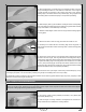
q Remove the protective backing from the covering material. With the control surface fully deflected in the 'UP' position, place the length of covering material over the hinge line (on the bottom), making sure that the crease is pushed completely down into the hinge line. IMPORTANT Only the bottom of the hinge gap needs to be sealed. It is not necessary to seal both the bottom and the top.
q Gently slide the wing joiner tube into the left wing panel until the wing joiner tube bottoms out. Step 3: installing the wing panels and retaining clips q Carefully slide the other end of the wing joiner tube through the fuselage and firmly push the wing panel up against the fuselage side. q Slide one rubber O-Ring over each of the two wing mounting posts, followed by one M6 flat washer.
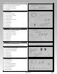
Step 1: Aligning the horizontal stabiliser q Remove the elevator halves from the stabiliser and set them aside for now. Discard the temporary hinges that are used for packing. q Cut away the covering material from over each side of the horizontal stabiliser mounting slot in the fuselage. The stabiliser mounting slot is 5/16" (8mm) tall and 3" (76mm) long. The front of stabiliser mounting slot is 7-3/8" (187mm) in front of the back of the fuselage.
q When you're satisfied that the stabiliser is square to the wing, use a T‑Pin to hold the front of the stabiliser firmly in place and aligned. q Look from the front of the aircraft at both the wing and the stabiliser. When aligned properly, the stabiliser should be parallel to the wing. B B-1 + If the stabiliser is not parallel to the wing, remove the stabiliser and sand down the higher side of the stabiliser mounting slot until you're satisfied with the alignment.
Step 3: Aligning and installing the Vertical stabiliser q Remove the rudder from the stabiliser and set it aside for now. Discard the temporary hinges that are used for packing. q Push the stabiliser down into the mounting slot, making sure that the rudder post is pushed firmly into the slot in the back of the fuselage. IMPORTANT When pushing the stabiliser into the mounting slot, be careful not to crack the rudder post at the base of the stabiliser.
Step 6: hinging the rudder q Hinge the rudder to the vertical stabiliser, using the same techniques that you used to hinge the elevator halves to the horizontal stabiliser. The rudder is hinged using three hinges and the bottom of the rudder should be even with the bottom of the fuselage. There should not be more than a 1/32" (.7mm) wide hinge gap. IMPORTANT Although you need to seal the aileron and elevator hinge gaps, it's not necessary to seal the rudder hinge gap.
q Drill three 5/64" (2mm) diameter pilot holes through the fuselage, then install the tail wheel mounting bracket, using three M3 x 12mm wood screws. q Thread the M2 x 12mm wood screw through the hole in the bottom of the steering arm mounting bracket and into the rudder, to secure the steering arm into place. IMPORTANT Apply a drop of thick C/A to the threads to help secure the wood screw more firmly.
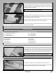
Step 1: installing the landing gear brackets q Install the two main landing gear brackets onto the fuselage, using six M4 x 12mm socket-cap screws and six M4 flat washers. q Install one threaded axle onto each landing gear bracket, using two M8 lock nuts. Make sure to tighten the lock nuts firmly to hold the threaded axles securely into place.
q Install one M3 blind nut into the wheel pant, then carefully apply a bead of thick C/A around the blind nut for extra security. PRO TIP Thread one M3 x 10mm machine screw and one flat washer into the blind nut, then tighten the machine screw to draw the blind nut into place. q Slide the wheel pant back into position and secure it to the landing gear bracket, using one M3 x 10mm machine screw.
IMPORTANT The precut mounting slots in the firewall are elongated to allow you to mount engines of varying width. To ensure that the engine lines up with the centre of the cowl, it's important that the engine mounts be centred within the precut mounting slots. q Line up the engine mounting beams within the precut slots in the firewall and temporarily install the four M4 x 25mm socket-cap screws, four M4 split washers, four M4 flat washers and four M4 blind nuts.
q Carefully bend the longer of the two aluminium tubes up at a shallow angle, being careful not to kink the tubing as you bend it. IMPORTANT When the stopper assembly is installed into the fuel tank, the top of the pressure tube (the tube you just bent) should rest just below the top of the fuel tank. q Secure one end of the silicone fuel tubing onto the end of the clunk. q Slide the silicone fuel tubing, with the clunk attached, onto the end of the aluminium fuel pick-up tube (straight tube).
THROTTLE CONTROL SYSTEM INSTALLATION You'll Need the following parts FROM THE KIT: q (1) 18" (457mm) Pushrod Wire with Z-Bend q (1) 1.5mm Hex Wrench q (1) Adjustable Pushrod Connector with Nut and Grub Screw You'll Need the following TOOLS AND SUPPLIES: q Thin C/A q Electric Drill q # 1 Phillips Head Screwdriver q 1/16" (1.
q Install the Z-Bend in the pushrod wire into the outermost hole in your engine's throttle arm, slide the pushrod wire through the hole that you drilled in the front of the fuselage, then reinstall your engine. IMPORTANT Depending on the engine you're using, it might be necessary to make a shallow bend in the pushrod wire to achieve perfect alignment, or to prevent the pushrod wire from hitting the side of the engine mounting box.
IMPORTANT This section details the installation of the push-pull rear mounted elevator control system. Use this option if you are using a heavier engine on the high end of the recommended size range. Mounting the servos in the back of the fuselage will help balance the aircraft by off-setting the added weight of the larger engine. If you prefer to install the pull-pull elevator control system with the servos mounted below the cockpit deck instead, please skip to the next section on page 25.
q Temporarily thread one M3 hex nut and one 3mm clevis onto each end of one 8-1/2" (216mm) threaded pushrod wire. q Centre the elevator servo and install a servo horn onto the servo, making sure that the servo arm is centred and points toward the bottom of the fuselage. Install the servo horn retaining screw to secure the servo horn to the servo. q Snap the clevis on one end of the threaded pushrod wire into the hole in the servo arm that is 3/4" (19mm) out from the centre of the servo horn.
ELEVATOR CONTROL SYSTEM INSTALLATION (PULL-PULL OPTION) You'll Need the following parts FROM THE KIT: q (2) Stranded Cables q (8) Crimp Collets q (2) M3 x 70mm Threaded Rods q (4) M3 Flat Washers q (4) Nylon Adjustable Control Horns q (4) M3 Lock Nuts q (4) Threaded Couplers q (4) M2 Hex Nuts q (4) Z-Bend Couplers q (1) Heat-Shrink Tubing q (4) Metal Clevises - 2mm Thread You'll Need the following TOOLS AND SUPPLIES: q Thin C/A q 1/16" (1.
q Slide one M3 flat washer onto the threaded rod and up against the lock nut, then push the threaded rod up through the control horn mounting hole. Slide a second M3 flat washer onto the threaded rod, then thread one M3 lock nut onto the threaded rod and tighten it firmly, making sure that the threaded rod is centred. Both ends of the threaded rod should be approximately 1-1/4" (32mm) from the surface of the elevator half.
q Enlarge the hole in each side of a servo horn that is 3/4" (19mm) out from the centre of the servo horn, using a 5/64" (2mm) diameter drill bit. q Install one Z-Bend coupler into the hole in each side of the servo horn that you enlarged. q Centre the elevator servo and install the servo horn onto the servo, making sure that it's centred, then install the servo horn retaining screw to secure the servo horn to the servo.
IMPORTANT It's important that both elevator halves track evenly together throughout the entire range of deflection. If one elevator half moves more than the other, this will cause the aircraft to roll when it pitches up or down during flight.
q Thread one 3mm lock nut onto the M3 x 70mm threaded rod so that the base of the lock nut is 1-3/16" (30mm) away from the end of the threaded rod. 1-3/16" (30mm) q Slide one M3 flat washer onto the threaded rod and up against the lock nut, then push the threaded rod through the control horn mounting hole. Slide a second M3 flat washer onto the threaded rod, then thread one M3 lock nut onto the threaded rod and tighten it firmly, making sure that the threaded rod is centred.
q Temporarily thread one M2 hex nut and one 2mm clevis onto each of the two threaded couplers, then feed the plain end of each of the two lengths of stranded cable through the slots in the fuselage and into the servo compartment. q Snap each clevis into the hole in the adjustable control horns, then firmly tighten the two hex nuts up against the clevises to lock the threaded coupler into place.
AILERON CONTROL SYSTEM INSTALLATION You'll Need the following parts FROM THE KIT: q (2) 2-3/8" (60mm) Threaded Pushrod Wires q (4) M3 Flat Washers q (2) M3 x 50mm Machine Screws q (2) M3 Lock Nuts q (2) Nylon Adjustable Control Horns q (4) M3 Hex Nuts q (4) Metal Clevises - 3mm Thread q (1) Heat-Shrink Tubing You'll Need the following TOOLS AND SUPPLIES: q # 1 and # 2 Phillips Head Screwdrivers q Straight Edge Ruler q Adjustable Wrench q Pencil q Modeling Knife q Masking Tape q Electric Drill
q Slide one M3 flat washer onto one M3 x 50mm machine screw, then push the machine screw up through the control horn mounting hole. Slide a second M3 flat washer onto the machine screw, then thread one M3 lock nut onto the machine screw and tighten it firmly. q Thread one nylon adjustable control horn onto the machine screw until the top of the control horn is 1/8" (3mm) below the end of the machine screw, then repeat the previous procedures to install the aileron control horn onto the other aileron.
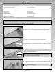
Step 1: aligning the cowl PRO TIP The Yak 54 ARF includes a clear mock-up cowl that can be used to make it easier to locate the necessary cutouts for your engine and muffler prior to actually cutting the fiberglass cowl. This is great for locating and transferring the initial cutouts to the fiberglass cowl; however, we suggest locating the holes for the cowl mounting screws using the method described in this section. This method will be more accurate than using the mock-up cowl.
q Remove the cowl from the fuselage, then measure forward from each of the lines that you drew to mark the back edge of the cowl to the centre of the predrilled hole in each of the cowl mounting blocks. Make a note of these measurements for the next procedure. q Measure the resulting distances forward from the back edge of the cowl and draw intersecting lines onto the cowl over the lines that you extended onto the cowl previously.
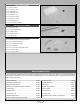
q Cut away the covering material from over both sides of the three flying wire bracket mounting holes in the horizontal and vertical stabilisers. One mounting hole is located in the vertical stabiliser, 5/8" (16mm) down from the top of the stabiliser and 3-1/8" (80mm) in front of the rudder hinge line. One mounting hole is located in each side of the horizontal stabiliser, 3-3/8" (86mm) in from the end of the stabiliser and 3/4" (19mm) in front of the elevator hinge line.
IMPORTANT When installing the metal eyelet onto the mounting bracket that's installed onto the fuselage in the procedure below, you will need to install the machine screw from the top of the mounting bracket. q Install one metal eyelet onto the mounting bracket that's installed on the fuselage, using one M3 x 10mm machine screw, two M3 flat washers and one M3 lock nut.
q Set the canopy onto the cockpit deck and align it. When aligned properly, the edges of the canopy should fit into the recess around the perimeter of the cockpit deck. It may be necessary to trim the edges of the canopy slightly for a perfect fit. q When satisfied with the alignment, use pieces of masking tape to hold the canopy firmly in place. q Secure the canopy to the cockpit deck, using a thin layer of Formula 560 Canopy Glue and nine M2 x 10mm flange-head wood screws.
C/G AND BALANCING IMPORTANT It is critical that your aircraft be balanced correctly. Incorrectly balancing your aircraft can cause your aircraft to lose control and crash! Balance Point (C/G): l 5-1/2" (140mm) back from the leading edge of the wing, measured at the fuselage sides. q Turn the aircraft upside down, place your fingers on the wing at the balance point, then carefully lift the aircraft. If the nose of the aircraft drops, the aircraft is nose heavy.
AIRCRAFT SETUP INFORMATION EXPONENTIAL Exponential (Expo) softens the control feel around neutral. This is especially helpful when flying an aircraft that uses a lot of control throw. Softening the neutral point makes the aircraft fly more smoothly and makes it more likely that you won't over-control. Please note that different brands of radio control systems may call for + or - Expo. Please refer to your radio control system's User's Guide for more information.
PREFLIGHT CHECK AND SAFETY l l Completely charge the transmitter and receiver batteries before your first day of flying. Check every bolt and every glue joint in the aircraft to ensure that everything is tight and well-bonded. This should include all of the control surface hinges as well. l Double-check that you've installed and tightened all of the servo horn retaining screws. l Use thread locking compound on all fasteners that thread into metal to prevent vibration from loosening them.
TRIM CHART After you have test-flown and done the initial trim changes to the aircraft, use this trim chart to begin trimming your aircraft. Following and adhering to this chart will result in the ability to diagnose trim problems and correct those problems using the simple adjustments shown below. Making these observations and related corrections will result in an aircraft that tracks straighter and flies truer.
THIS PAGE INTENTIONALLY LEFT BLANK Page 42
PRODUCT EVALUATION SHEET Telling us what you like and don't like determines what model kits we make and how we make them. We would appreciate it if you would take a few minutes of your time to answer the following questions about this kit and your modeling interests. Simply fold this form on the dotted lines, seal with tape and mail it to us. Do not use staples and make sure our address faces out. Global Hobby Distributors will not disclose the information it collects to outside parties.
Fold along dotted line ______________________________ ______________________________ ______________________________ Post Office will not deliver without proper postage (Return Address Here) Global Hobby Distributors Attn: Global Services 18480 Bandilier Circle Fountain Valley CA 92728-8610 Fold along dotted line Page 44