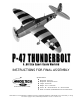
INSTRUCTIONS FOR FINAL ASSEMBLY Specifications: Product Part Number 123745 ● Wing Span: 67 Inches ● Wing Area: 785 Square Inches ● Length: 55.5 Inches ● Weight: 6.75 - 7.75 Pounds ● Power: .61 - .91 Two Stroke or .70 - .
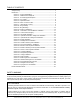
TABLE OF CONTENTS Safety Warning .......................................................................................................... 2 Introduction ............................................................................................................... 3 Section 1: Our Recommendations .................................................................... 4 Section 2: Additional Items Required ...............................................................
INTRODUCTION Thank you for purchasing the new Modeltech P-47 Thunderbolt ARF. Before completing the final assembly of your new airplane, please carefully read through this instruction manual in its entirety.
SECTION 1: OUR RECOMMENDATIONS This section describes our recommendations to help you in deciding which types of accessories to purchase for your new P-47 Thunderbolt ARF. These suggestions are not set in stone, but they should provide you with a good starting point. What Engine Should I Use? If you Want to Use a Two Stroke Engine: If you want to use a two stroke engine, we recommend using a .61 up to a .91. A strong ball bearing .
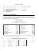
SECTION 2: ADDITIONAL ITEMS REQUIRED Here's a List of What We Used in the Airplane Shown in These Instructions: QTY. 1 210803 Magnum XL .61ARNV Engine QTY. 1 444222 Cirrus CS-100 Retract Servo QTY. 1 280180 Magnum Pitt's Style Muffler QTY. 2 444713 Cirrus 12" Aileron Extensions QTY. 1 280153 Magnum Muffler Extension QTY. 1 444728 Cirrus Y-Harness QTY. 1 609288 APC 13 x 6 Propeller QTY. 1 115923 Global Silicon Fuel Tubing QTY. 1 115493 Thunderbolt R/C Long Glow Plug QTY.
SECTION 4: KIT CONTENTS We have organized the parts as they come out of the box for easier identification during assembly. Before you begin assembly, group the parts like we list them below. This will ensure that you have all of the parts before you begin assembly and it will also help you become familiar with each part.
WING ASSEMBLY FUEL TANK ASSEMBLY ❑ (1) Plywood Dihedral Brace (W64) ❑ (1) 360cc Fuel Tank ❑ (1) Plywood Wing Bolt Doubler (W72) ❑ (1) 20mm Diameter Aluminum Front-Plate ❑ (2) 5mm x 35mm Machine Screws ❑ (1) 18mm Diameter Aluminum Back-Plate ❑ (2) 5mm Flat Washers ❑ (1) Rubber Stopper ❑ (2) 5mm Blind Nuts ❑ (1) Silicon Fuel Tubing ❑ (1) Weighted Fuel Pick-Up ❑ (2) Aluminum Tubes ❑ (1) 3mm x 20mm Machine Screw RETRACT LANDING GEAR ASSEMBLY ❑ (2) Retract Assemblies wi
MISCELLANEOUS PARTS ❑ (1) Polished Aluminum Spinner Hub - 5/16" ❑ (1) Plastic Machine Gun Fairings ❑ (1) Plywood Fuselage Servo Tray (D24) ❑ (6) 3mm x 5mm Wood Screws ❑ (1) Precovered Tail Wheel Hatch Cover ❑ (2) Clear Tubing ❑ (4) Hardwood Cowl Mounting Blocks (D25) ❑ (1) Nylon Antenna ❑ (5) 3mm x 12mm Wood Screws ❑ (1) Decal Set ❑ (4) 3mm Flat Washers SECTION 5: REPLACEMENT PARTS Modeltech stocks a complete line of replacement parts for your P-47 Thunderbolt ARF.
SECTION 7: A NOTE ABOUT COVERING The covering material used on the P-47 Thunderbolt ARF is real iron-on heat shrink covering material, not cheap "shelf paper." Because of this, it is possible with heat and humidity changes that the covering on your airplane may wrinkle or sag. This trait is inherent in all types of heat shrink material. To remove any wrinkles that might be visible you will need to purchase, or borrow from a fellow modeler, a heat iron.
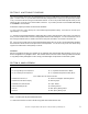
❑ Using a modeling knife, cut away and remove the excess covering material that overlaps onto the root ribs of each wing panel, leaving about 1/16" overlapped so it does not pull away. IMPORTANT It's very important to the integrity of the wing center section joint that you remove as much covering from the root ribs as possible. ❑ Use a ruler and a pencil to locate and draw a vertical centerline on each side of the plywood dihedral brace. ❑ Test-fit the dihedral brace into each wing panel.
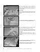
❑ Look carefully at the center section joint: the wing halves should fit together tightly with few or no gaps in the joint. ☞ If the wing halves do not fit together properly, remove the dihedral brace and use 220 grit sandpaper with a sanding block to lightly sand the edges and tips of the brace. ❑ When satisfied with the fit, pull the wing panels apart and remove the dihedral brace. Step 2: Joining the Wing Panels When joining the wing panels together, use only 30 minute or more epoxy.
Step 4: Installing the Plywood Wing Bolt Doubler ❑ Set the wing bolt doubler onto the bottom of the wing. The rear edge of the doubler should be 3/32" in front of the trailing edge of the wing and the centerline of the doubler should be lined up with the centerline of the wing. ☞ The groove in the doubler (centerline) should face away from the surface of the wing. ❑ While holding the doubler in place, use a pencil to draw an outline of the doubler onto the wing's surface.
❑ Using a ruler and a pencil, measure out 1-1/2" from each side of the wing centerline (at the trailing edge) and draw a mark on the plywood wing bolt doubler. ❑ Using a ruler and a pencil, measure forward 1/2" from the back edge of the wing bolt doubler (at the first marks you drew) and draw two intersecting marks. ☞ Where the marks intersect is the location of the wing hold-down screws. ❑ Set the fuselage upside down securely in your airplane stand.
Step 2: Tapping the Wing Mounting Block IMPORTANT Although the P-47 includes blind nuts to install in the wing mounting block, we suggest tapping the block with a 5mm tap as we show. This is much easier than installing the blind nuts and is more accurate. Of course, you can opt to install the blind nuts if you want to. ❑ Using a 5/32" drill bit, carefully drill two holes into the wing and through the plywood wing mounting block inside the fuselage.
Step 3: Mounting the Wing ❑ Using a 13/64" drill bit, enlarge only the two wing mounting holes in the wing. ☞ Enlarging the holes will allow the wing bolts to slide through the wing without binding. ❑ Set the wing back into the wing saddle and realign it. ❑ Secure the wing into place using two 5mm x 35mm machine screws and two 5mm flat washers. ☞ Don't overtighten the screws. You don't want to crush the wing.
IMPORTANT You may need to sand an angle in the front of the belly pan so that it will fit flush with the surface of the wing. ❑ If there are any gaps between the belly pan and the wing, remove the belly pan and sand down any high spots using a sanding block with 220 grit sandpaper. Remove small amounts of material at a time, checking the fit often.
❑ Glue the belly pan into place using a generous amount of 5 minute epoxy. Remove any excess epoxy using a paper towel and rubbing alcohol, and hold the belly pan firmly in place and aligned using pieces of masking tape until the epoxy fully cures. WARNING Make sure you don't get epoxy between the wing and/or belly pan and the fuselage.
❑ While holding the vertical stabilizer firmly in place, use a builder's triangle to double-check that the vertical stabilizer is aligned 90º to the horizontal stabilizer. Step 2: Mounting the Vertical Stabilizer ❑ Mix and apply a generous amount of 30 minute epoxy to the bottom of the vertical stabilizer and to the slot in the trailing edge of the horizontal stabilizer. ❑ Push the stabilizer down into place and realign it, double-checking all of your measurements once more before the epoxy sets up.
❑ With the stabilizer assembly held firmly in place, look from the front of the airplane at both the wing and the horizontal stabilizer. When aligned properly, the horizontal stabilizer should be parallel with the wing. C=C-1 IMPORTANT If the stabilizer assembly is out of alignment, remove it and use 220 grit sandpaper with a sanding block to sand down the higher mounting side on the fuselage, then reinstall the assembly and check the alignment once more.
SECTION 12: CONTROL SURFACE HINGING YOU'LL NEED THE FOLLOWING PARTS: ❑ (17) C/A Style Hinges YOU'LL NEED THE FOLLOWING SUPPLIES: ❑ Kwik Bond Thin C/A ❑ Kwik Bond C/A Debonder ❑ Ernst Airplane Stand ❑ Paper Towels IMPORTANT If you want flutter-free control surfaces it is imperative that the hinges be glued in properly. This includes both having a tight hinge gap and using plenty of thin C/A glue. Step 1: Hinging the Ailerons ❑ Slide one hinge into each of the four hinge slots in each aileron.
❑ Repeat the previous procedures to install the second aileron on the other half of the wing. Step 2: Hinging the Elevator Halves and Rudder ❑ Hinge the elevator halves and the rudder using the same methods as for the ailerons. When aligned properly, the outer tips of the elevator halves and rudder should be even with the tips of the stabilizers. Be sure to check the integrity of the hinges, after the C/A has fully cured, by pulling gently on the control surfaces.
❑ Install the tail wheel assembly into the back of the fuselage using four 3mm x 15mm socket-cap screws and four 3mm flat washers. Tighten the screws firmly using a 1.5mm hex wrench. ☞ Blind nuts have been preinstalled in the back side of the bulkhead to accept the screws. Step 2: Installing the Tail Wheel ❑ Slide one 3mm nylon spacer onto the tail wheel wire, followed by the 40mm diameter tail wheel. Use one 3mm wheel collar and one 3mm x 5mm machine screw to hold the wheel in place.
❑ Insert the short 90º bend in each main gear wire into the predrilled hole in each landing gear block. ❑ Push the wires firmly down into the slots. ☞ The top of the wires should be nearly flush with the top of the blocks. ☞ When the landing gear wires are pushed into place, they come out of the blocks at an angle. This is normal and is necessary for the wheels to line up under the leading edge of the wing.
Step 2: Installing the Nylon Landing Gear Straps ❑ Each main gear wire is held in place using two flat nylon landing gear straps and four 3mm x 12mm wood screws. Working with one gear wire for now, position two straps equal distances from each end of the wire. ❑ While holding the straps in place, use a pencil to mark the locations of the mounting screws on the landing gear block. ❑ Remove the nylon straps and drill four 5/64" pilot holes into the landing gear block.
❑ Install the covers onto the landing gear wires using four U-shaped nylon gear cover straps, eight 3mm x 10mm machines screws, eight 3mm flat washers and eight 3mm hex nuts. ☞ The covers should be perpendicular to the landing gear axles and there should be a 1/8" gap between the front edge of the gear covers and the wing. Step 4: Installing the Main Gear Wheels ❑ Slide one 4mm nylon spacer onto each axle followed by one 60mm diameter wheel, recessed side toward the nylon spacer.
❑ Test-fit the retract servo onto the servo mounting rails, making sure the servo output shaft is toward the trailing edge of the wing. ☞ The servo should be centered on the servo rails as shown. Because servo sizes differ, you may need to trim the inside edges of the servo rails to fit your particular servo. ❑ Drill 1/16" pilot holes through the servo rails and install the retract servo using the wood screws provided with your servo.
❑ Using a modeling knife and a ruler, cut away and remove the portion of the wing for strut clearance. IMPORTANT Make the slot slightly wider than the strut to prevent any chance of the strut interfering with the wing during use. ❑ Install the Z-Bend in one 2mm x 250mm pushrod wire into the hole in the nylon retract actuator arm. ❑ Using a pair of pliers, make a 7/8" deep bend in the pushrod wire as shown. Make the bend 2" out from the Z-Bend.
Step 3: Connecting the Pushrod Assemblies ❑ Install two adjustable servo connectors onto a large servo wheel. Each connector should be installed in a hole that is 7/16" out from the center of the wheel. IMPORTANT When threading on the connector nuts, don't tighten them completely. You don't want the connectors loose, but you do want them to be able to rotate without binding. ☞ You will have to enlarge the holes in the servo wheel using a 5/64" drill bit to accommodate the connectors.
Step 4: Installing the Main Gear Wheels ❑ Slide one 60mm wheel, flat side toward the wing tip, onto each axle. ❑ Slide one 4mm nylon spacer onto each axle, up against the wheel. ❑ Secure each wheel in place using one 4mm wheel collar and one 3mm x 5mm machine screw. Tighten the screws firmly to secure the wheels in place.
❑ Cycle the retracts up and down a couple of times to check the alignment. The wheel should be centered within the wheel cup and no part of the strut should touch the wing. ❑ When satisfied with the alignment, glue the wheel cup into place using Pacer Formula 560 Canopy Glue. ❑ Repeat the previous procedures to install the second wheel cup in the other half of the wing. There are four precovered retract cover-plates (W70) included with your P-47.
Before continuing you should decide in which direction you want to mount your engine. The direction you mount your engine is strictly up to you. You can either mount the engine sideways (like we show), inverted, or at a 45º down angle. Whichever direction you decide to mount the engine make sure that the center of the engine's crankshaft lines up where the horizontal and vertical lines intersect. This will ensure that the crankshaft will be lined up with the cowling when it is installed later.
Step 2: Installing the Engine Mount Beams ❑ Remove the engine mount beams from your engine and clean off any dried C/A from the engine mount beams and the bottom of the engine mounting lugs using a modeling knife. ❑ Using a drill with an 11/64" drill bit, drill a hole through the firewall at each of the four intersecting lines. IMPORTANT If you are using a short engine like a .61 two stroke or a new-generation .
Before marking and drilling the holes for the engine mounting screws in the next few procedures, it's very important to verify that the engine's thrust washer is 5-5/8" away from the firewall. This will ensure that the front of the cowling lines up properly when it is installed later. This measurement is universal for all engines, both two and four strokes. ❑ While holding the engine firmly in place, use a pencil to mark the locations of the four engine mounting screws onto the engine mount beams.
SECTION 17: FUSELAGE SERVOS INSTALLATION YOU'LL NEED THE FOLLOWING PARTS: ❑ (1) Plywood Fuselage Servo Tray (D24) YOU'LL NEED THE FOLLOWING SUPPLIES: ❑ Kwik Bond Thick C/A ❑ Electric Drill ❑ # 1 Phillips Head Screwdriver ❑ 1/16" Drill Bit ❑ Excel Modeling Knife ❑ Ernst Airplane Stand Step 1: Installing the Fuselage Servo Tray ❑ Test-fit the servo tray onto the two preinstalled support rails inside the fuselage. The sides of the tray should be equal distances from the sides of the fuselage.
SECTION 18: THROTTLE CONTROL SYSTEM INSTALLATION YOU'LL NEED THE FOLLOWING PARTS: ❑ (1) 2mm x 400mm Pushrod Wire w/Z-Bend ❑ (1) Adjustable Servo Connector Assembly YOU'LL NEED THE FOLLOWING SUPPLIES: ❑ Kwik Bond Thin C/A ❑ Electric Drill ❑ # 1 Phillips Head Screwdriver ❑ 5/64" & 7/64" Drill Bits ❑ Wire Cutters ❑ Ernst Airplane Stand ❑ Excel Modeling Knife Step 1: Installing the Throttle Pushrod Wire ❑ Carefully drill a 7/64" hole through the firewall for the throttle pushrod wire to enter the en
Step 2: Installing the Adjustable Servo Connector ❑ Using wire cutters, remove all but one arm from a "4-point" servo horn. ❑ Enlarge the fourth hole out from the center of the servo arm using a 5/64" drill bit. ❑ Install the adjustable servo connector into the servo arm. IMPORTANT When threading on the connector nut, don't tighten the nut completely. You don't want the connector loose, but you do want it to be able to rotate without binding.
SECTION 19: FUEL TANK ASSEMBLY & INSTALLATION YOU'LL NEED THE FOLLOWING PARTS: ❑ (1) 360cc Fuel Tank ❑ (1) Silicon Fuel Tubing ❑ (1) 20mm Diameter Aluminum Front-Plate ❑ (1) Weighted Fuel Pick-Up ❑ (1) 18mm Diameter Aluminum Back-Plate ❑ (2) Aluminum Tubes ❑ (1) Rubber Stopper ❑ (1) 3mm x 20mm Machine Screw YOU'LL NEED THE FOLLOWING SUPPLIES: ❑ # 1 Phillips Head Screwdriver ❑ Ruler ❑ Promax Canopy Scissors ❑ 220 Grit Sandpaper w/Sanding Block ❑ Ernst Airplane Stand Step 1: Assembling the Rubbe
❑ Slide the 20mm diameter front-plate over the ends of the aluminum tubes and push it against the front of the stopper. ❑ Push the 3mm x 20mm machine screw into the frontplate and through the stopper assembly, then partially thread it into the back-plate. ❑ Attach the clunk to one end of the silicon fuel tubing. ❑ Attach the fuel tubing onto the end of the aluminum fuel pick-up tube (straight tube).
❑ Double-check the seal between the stopper and the fuel tank. To do this, carefully try to twist the stopper assembly. If the stopper twists in the fuel tank, tighten the machine tighter. If the stopper doesn't twist, the seal is good. ❑ With the stopper assembly in place, double-check to make sure the clunk can move freely inside the fuel tank. Ideally, the clunk should be about 1/4" - 3/8" in front of the back of the tank.
SECTION 20: ELEVATOR CONTROL SYSTEM INSTALLATION YOU'LL NEED THE FOLLOWING PARTS: ❑ (2) 755mm Nylon Pushrod Tubes ❑ (1) Nylon Pushrod Joiner Plate ❑ (2) 2mm x 255mm Threaded Wires ❑ (2) 2mm x 10mm Flange-Head Wood Screws ❑ (2) Nylon Control Horns w/Backplates ❑ (2) 2mm Flat Washers ❑ (4) 2mm x 25mm Machine Screws ❑ (1) 2mm Hex Nut ❑ (1) 2mm x 20mm Machine Screw ❑ (1) Clear Tubing ❑ (3) Nylon Clevises YOU'LL NEED THE FOLLOWING SUPPLIES: ❑ Kwik Bond Thin C/A ❑ Electric Drill ❑ # 1 Phillips Head
❑ Install the nylon control horn using two 2mm x 25mm machine screws. ☞ Don't overtighten the screws. You don't want to crush the elevator. ❑ Repeat the previous procedures to install the second control horn on the other elevator half. Step 2: Installing the Elevator Pushrod Tubes ❑ Install one 2mm x 20mm machine screw, two 2mm flat washers and one 2mm hex nut into the center hole in the nylon pushrod joiner plate. Tighten the assembly securely.
❑ Slide the plain end of one 2mm x 255mm threaded wire into the back of each nylon pushrod tube. ❑ Thread the wires into the tubes until 1/2" of threaded wire extends past the end of each tube. ❑ Apply a couple of drops of thin C/A to the ends of the tubes. The C/A will "wick" into the tubes, securing the wires firmly in place. ❑ Using a modeling knife, remove the covering from over the elevator pushrod exit hole in each side of the fuselage.
❑ Check the control surface throw by measuring from the widest point of each control surface. Both elevator halves should move both up and down 3/8". ☞ You can adjust the control throws by moving the clevises in and out on both the control horns and the servo arm. Moving the clevises toward the control surfaces will increase the control throw. Moving them away will decrease the throw.
Step 2: Installing the Rudder & Steering Pushrod Tubes The rudder and steering pushrod control system is assembled in the same manner as the elevator pushrod control system, however, because the steering pushrod clevis is difficult to access once the pushrod is installed, the assembly order of the rudder and steering control system will be different. ❑ Install one 2mm x 255mm threaded wire into one end of each nylon pushrod tube.
❑ Using wire cutters, remove all but one arm from a "4-point" servo horn. ❑ Snap the nylon clevis (attached to the joiner plate assembly) into the second hole out from the center of the servo arm. ☞ You will have to enlarge the hole in the servo arm using a 5/64" drill bit so the clevis does not bind. ❑ Connect your radio system and plug the rudder servo into its proper slot in the receiver. Double-check that the rudder trim lever on your transmitter is centered.
SECTION 22: AILERON CONTROL SYSTEM INSTALLATION YOU'LL NEED THE FOLLOWING PARTS: ❑ (2) Plywood Servo Covers (W59) ❑ (2) Nylon Clevises ❑ (4) Servo Mounting Blocks (W60) ❑ (2) Nylon Snap-Keepers ❑ (2) 2mm x 60mm Threaded Wires w/90º Bends ❑ (8) 3mm x 5mm Wood Screws ❑ (2) Nylon Control Horns w/Backplates ❑ (1) Clear Tubing ❑ (4) 2mm x 30mm Machine Screws YOU'LL NEED THE FOLLOWING SUPPLIES: ❑ Kwik Bond 5 Minute Epoxy ❑ Pencil ❑ # 1 Phillips Head Screwdriver ❑ Masking Tape ❑ Needle Nose Pliers ❑
❑ Temporarily place the aileron servo onto the bottom (noncovered side) of the servo cover. The servo arm should be inserted through, and centered within, the precut slot. ❑ While holding the servo aligned, temporarily place two hardwood mounting blocks behind the servo mounting tabs. ☞ You will need to first cut a notch in one of the blocks so the block doesn't interfere with the servo wire.
Step 2: Installing the Servo Cover Assemblies ❑ Using a modeling knife, cut away and remove the covering material from over the two aileron servo hatches in the bottom of the wing. ❑ Turn the wing over and remove the covering material from over the two servo lead exit holes in the top of the wing. Each hole is 5/8" in diameter and is located 1-3/4" out from the centerline of the wing and 7-3/8" in front of the trailing edge. ❑ Install one 12" servo extension lead onto each of the two aileron servo leads.
❑ Remove the servo cover assembly and enlarge only the holes in the servo cover using a 3/32" drill bit. ❑ Reinstall the servo cover assembly using the four 3mm x 5mm wood screws provided. ❑ Repeat the previous procedures to install the second servo cover assembly in the other half of the wing. Step 3: Installing the Aileron Pushrods ❑ Enlarge the fourth hole out from the center of one control horn using a 5/64" drill bit.
❑ Cut one 1/4" long piece of clear tubing and slide it onto the base of one nylon clevis. ❑ Thread the clevis onto the pushrod wire and snap the clevis into the fourth hole out from the base of the control horn. ❑ Slide the clear tubing up over the clevis to keep it from opening during flight. ❑ Repeat the procedures above to install the second control horn and clevis assembly.
SECTION 23: COWLING INSTALLATION YOU'LL NEED THE FOLLOWING PARTS: ❑ (1) Molded Fiberglass Cowling ❑ (4) 3mm x 12mm Wood Screws ❑ (4) Hardwood Cowl Mounting Blocks (D25) ❑ (4) 3mm Flat Washers YOU'LL NEED THE FOLLOWING SUPPLIES: ❑ Kwik Bond 5 Minute Epoxy ❑ Dremel Tool w/Sanding Drum & Cutting Disc ❑ # 1 Phillips Head Screwdriver ❑ 220 Grit Sandpaper w/Sanding Block ❑ Excel Modeling Knife ❑ Masking Tape ❑ Electric Drill ❑ Paper Towels ❑ 1/16", 5/64" & 5/16" Drill Bits ❑ Rubbing Alcohol ❑ Erns
❑ Carefully slide the cowling over the engine and onto the fuselage. The back edge of the cowling (at the top and upper sides) should overlap the front of the fuselage 1-1/4". ☞ Depending on the size of the engine you've chosen, you may need to cut away a portion of the cowling to clear the engine's cylinder head. If so, use a Dremel tool with a cutting disc and a sanding drum to make the cutout. Work slowly, checking the fit often so you don't remove too much of the cowling or damage it.
❑ Before permanently installing the cowling you should make the rest of the cut-outs for your engine. These include cut-outs for the high and low speed needle valves, muffler assembly and in-cowl fueling valve assembly. If your engine is mounted sideways you will need to attach a short piece of wire to your needle valve to make mixture adjustments.
❑ Cut out the front and back of the wing fairings, being careful to follow the molded edges closely. ❑ Cut the outer edge of the wing fairings along the molded scribe line. ❑ Sand the edges of the wing fairings smooth and straight using 220 grit sandpaper with a sanding block. Step 2: Installing the Balsa Support Braces ❑ Bolt the wing securely to the fuselage. ❑ Test-fit one wing fairing onto the wing.
❑ Using a modeling knife, rough-cut the support block close to its final shape. ❑ Sand the support block smooth and straight using 220 grit sandpaper and a sanding block. ☞ You want the support block to be straight across from the inside edge to the outside edge. ❑ Test-fit balsa support block W74 into the middle of the wing fairing. Note the angle the block is installed at. ❑ Glue the block into place, then trim it to shape using the same technique as before.
❑ Remove the wing fairing and carefully cut away and remove the covering material on the wing from within the outline you drew. ❑ Glue the wing fairing into place using 5 minute epoxy. Quickly remove any excess epoxy using a paper towel and rubbing alcohol, and use pieces of masking tape to hold the wing fairing securely in place. WARNING Be very careful not to get any epoxy between the wing fairing and the fuselage side.
❑ Carefully drill four 1/16" pilot holes through the canopy and into the fuselage for the mounting screws. Locate three holes on each side of the canopy, equally spaced apart. ❑ Remove the canopy and enlarge only the holes in the canopy using a 5/64" drill bit. IMPORTANT If you have decided to install an optional pilot and/or instrument panel, do so now before gluing the canopy into place in the next procedure. ❑ Apply a thin bead of Pacer Formula 560 Canopy Glue around the inside base of the canopy.
❑ Test-fit the machine gun fairings to the leading edge of each wing half. The center of each fairing should be 14" out from the centerline of the wing. ❑ When satisfied with the fit, glue the fairings to the leading edge of the wing using a generous amount of Formula 560 Canopy Glue. Remove any excess glue using a paper towel soaked with water, and use pieces of masking tape to hold the fairings in place until the glue completely dries.
❑ Secure the hatch cover into place using one 3mm x 12mm wood screw. Don't overtighten the screw or you will crush the wood. Step 4: Installing the Propeller and Spinner Hub ❑ Slide the propeller onto the crankshaft and thread on the spinner hub. Tighten the spinner hub firmly by sliding a thin-shank screwdriver through the hole in the spinner hub and twisting like a wrench. ☞ It's unnecessary (and not recommended) to use the propeller washer behind the spinner hub.
Step 7: Applying the Decals ❑ Using a clean cloth, wipe the airframe down completely to remove dust, debris and oil. ❑ Working with one decal at a time, use a pair of scissors and carefully cut out the decal along its outer edges. ❑ Remove the protective backing from the decal and stick the decal to the airplane. (Use the box cover photos to position the decals.) Lightly rub the decal with a soft cloth to remove any trapped air from beneath it.
SECTION 28: LATERAL BALANCING THE P-47 THUNDERBOLT ☞ Lateral balancing will make the airplane easier to trim and will make it track straighter in the air. It is strongly recommended. ❑ Turn the airplane upside down and tie one length of string to the propeller shaft and one length of string to the tail wheel wire. ❑ With someone helping you, carefully lift the airplane up by the two pieces of string. Watch how the wing reacts. If one side of the wing drops, that side is heavier than the other.
SECTION 30: PREFLIGHT CHECK & SAFETY ● Completely charge the transmitter and receiver batteries before your first day of flying. ● Check every bolt and every glue joint in the airplane to ensure that everything is tight and well-bonded. This should include all of the control surface hinges as well. ● Double-check the balance of the airplane. Do this with the fuel tank empty. ● Check the control surfaces. They should all move in the correct direction and not bind.
SECTION 31: FLYING THE P-47 THUNDERBOLT The Modeltech P-47 Thunderbolt 60 ARF is designed for those pilots who are experienced at flying sport models. It is not a trainer. If you do not feel comfortable that you are able to test fly the airplane, don't hesitate to ask someone for some help test-flying and trimming it. When set up for test-flying or general sport flying, the P-47 is much like flying any other sport airplane. It's a nimble flyer that, for its size, has a low wing loading.
Need help or have any questions? Call us at 1-714-963-0329 or send us an Email at service@globalhobby.
See other exciting Modeltech ARF airplanes at http://modeltech.globalhobby.
Need help or have any questions? Call us at 1-714-963-0329 or send us an Email at service@globalhobby.
PRODUCT EVALUATION SHEET Telling us what you like and don't like determines what model kits we make and how we make them. We would appreciate it if you would take a few minutes of your time to answer the following questions about this kit and your modeling interests. Simply fold this form on the dotted lines, seal with tape and mail it to us. Do not use staples and make sure our address faces out. Global Hobby Distributors will not disclose the information it collects to outside parties.
Fold along dotted line _____________________________ _____________________________ _____________________________ Post Office will not deliver without proper postage (Return Address Here) Global Hobby Distributors Attn: Customer Service 18480 Bandilier Circle Fountain Valley CA 92728-8610 Fold along dotted line 68 Need help or have any questions? Call us at 1-714-963-0329 or send us an Email at service@globalhobby.