
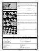
Specifications

Page 8
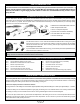
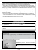
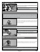
q Cut away the covering material from over the two elevon servo mounting
holes in the bottom of the wing. One servo mounting hole is located on each
side of the wing, 1/2" (13mm) out from the sides of the radio compartment and
6" (152mm) in front of the elevon hinge lines.
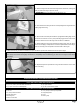
q Working with one elevon servo for now, run the servo lead through the
precut slot in the inboard side of the servo mounting hole and into the radio
compartment.
q Position and mark the mounting hole locations for the control horn on the
bottom of one elevon. When aligned properly, the centreline of the control horn
should be positioned 1-1/4" (32mm) out from the inboard edge of the elevon
(measured at the hinge line) and the clevis attachment holes should be lined
up over the hinge line. The base of the control horn should be parallel to the
hinge line, too.
q Drill 5/64" (2mm) diameter pilot holes through the elevon for the control horn
mounting screws, then apply a couple of drops of thin C/A into the pilot holes.
Allow the C/A to fully cure.
+
The C/A will harden the surrounding wood, making the mounting area
stronger.
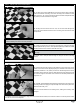
q Install the control horn and backplate, using three M2 x 16mm machine screws, then use wire cutters to cut the top of the screws
ush with the control horn backplate.
IMPORTANT Depending on the dimensions of your elevon servo, you may need to cut the servo mounting hole slighly larger to
t before installing the servo in the next procedure.
q Install your elevon servo into the servo mounting hole, using the mounting
screws provided with your servo, then repeat the previous procedures to install
the second elevon servo into the other half of the wing.
IMPORTANT The servo output shaft should be toward the front of
the wing.
+
Make sure to drill pilot holes through the wing for the servo mounting
screws.