ASSEMBLY INSTRUCTIONS Check out our website for more information on other exciting Model Tech products! http://modeltech.globalhobby.com features Model Tech Co., Ltd. Hong Kong © 2008, Model Tech Co., Ltd.
TABLE OF CONTENTS INTRODUCTION...........................................................................2 ELEVON CONTROL SYSTEM INSTALLATION............................7 SAFETY WARNING......................................................................2 LANDING SKID AND MOTOR INSTALLATION............................9 OUR GUARANTEE.......................................................................2 VERTICAL STABILISERS INSTALLATION.................................12 OUR RECOMMENDATIONS..........
OUR RECOMMENDATIONS This section describes our recommendations to help you in deciding which types of accessories to purchase for your new aircraft. Please read through this entire section very carefully. We have provided you with recommendations that, if followed, will result in a great flying aircraft. Failure to follow our recommendations may result in a poor flying aircraft.
LITHIUM POLYMER BATTERY WARNINGS - PLEASE READ WARNINGS AND SAFETY PRECAUTIONs FOR ALL BRANDS OF LITHIUM POLYMER BATTERIES Please read and understand the warnings listed in this section. Make sure to read any and all warnings included in the packaging with your battery, too. If used improperly, lithium polymer batteries can be very dangerous, so please follow these warnings and suggestions at all times. This product may explode or catch fire. Serious injury can result from misuse.
TOOLS AND SUPPLIES REQUIRED q 5 Minute Epoxy q 220 Grit Sandpaper q Thin and Thick C/A q Sanding Block q C/A Debonder q Masking Tape q Formula 560 Canopy Glue q Paper Towels q # 1 and # 2 Phillips Head Screwdrivers q Rubbing Alcohol q Wire Cutters q Epoxy Mixing Sticks q Needle Nose Pliers q Epoxy Mixing Cups q Modeling Knife q Soldering Iron q Scissors q Solder q Electric or Hand Drill q Heat-Shrink Tubing (Assorted Sizes) q Assorted Drill Bits q Heat Gun (for Heat-Shrink Tubing) q St
TIPS FROM THE PROS During the covering process, sometimes color may smear slightly from the seams. If you see any smeared colors on the covering material, they can be quickly removed by simply wiping them off with a paper towel and a small amount of acetone. l l Make sure to test-fit the parts together before applying glue. This will ensure that the parts fit properly before gluing them together.
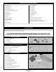
q Slide one hinge into each of the three hinge slots in the elevon, making sure that you push each hinge in up to the T-Pins. IMPORTANT Don't glue the hinges into the elevon yet. q Push the elevon and hinges into the corresponding three hinge slots in the trailing edge of the wing. q Remove the T-Pins and push the elevon up against the trailing edge. There should be no more than a 1/32" (.7mm) wide hinge gap and the outer end of the elevon should not touch the wing when the elevon is deflected.
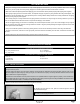
Step 1: installing the elevon servos q Cut away the covering material from over the two elevon servo mounting holes in the bottom of the wing. One servo mounting hole is located on each side of the wing, 1/2" (13mm) out from the sides of the radio compartment and 6" (152mm) in front of the elevon hinge lines. q Working with one elevon servo for now, run the servo lead through the precut slot in the inboard side of the servo mounting hole and into the radio compartment.
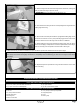
q Enlarge the hole in one servo arm that is 3/8" (10mm) out from the centre of the servo horn, using a 1/16" (1.6mm) diameter drill bit. q Install the Z-Bend in one pushrod wire into the hole that you enlarged in the servo arm. + The pushrod wire should be orientated on top of the servo arm. q Use a couple of pieces of masking tape, taped between the elevon and the wing, to hold the elevon centred.
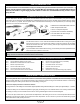
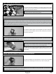
Step 1: installing the landing skid q Cut away the covering material from over the landing skid mounting slots in the bottom of the wing, then test-fit and glue the landing skid firmly into place, using a generous amount of thick C/A. IMPORTANT Make sure to cut away the covering material from over the gluing surfaces to ensure a strong bond. Step 2A: installing the motor - with bolt-on threaded propeller adapter IMPORTANT Two different types of motor are showed installed.
q Install your motor, using four M3 x 12mm machine screws and four M3 flat washers, making sure to tighten the machine screws firmly. IMPORTANT It's not necessary to use the two plywood spacer plates with this type of motor. Step 3: installing the cowling q Cut out the back of the cowling along its base, making sure to cut the back edge straight.
VERTICAL STABILISERS INSTALLATION You'll Need the following parts FROM THE KIT: q (2) Vertical Stabilisers You'll Need the following TOOLS AND SUPPLIES: q 5 Minute Epoxy q Paper Towels q Modeling Knife q Rubbing Alcohol q Straight Edge Ruler q Epoxy Mixing Sticks q Pencil q Epoxy Mixing Cups q Builder's Triangle Step 1: Aligning the Vertical stabilisers q Cut away the covering material from over the two vertical stabiliser mounting slots in the top of the wing.
FINAL ASSEMBLY You'll Need the following parts FROM THE KIT: q (1) Hook and Loop Material q (1) Canopy You'll Need the following TOOLS AND SUPPLIES: q Formula 560 Canopy Glue q Paper Towels q # 2 Philips Head Screwdriver q Soldering Iron q Wire Cutters q Solder q Modeling Knife q Heat Shrink q Scissors q Heat Gun q Straight Edge Ruler q Heat Sealing Iron q 220 Grit Sandpaper with Sanding Block q White Covering Material 1/2" x 24" (1.
Step 3: installing the flight battery q Carefully solder matching plugs onto the two battery wires on your battery and the two battery wires on your ESC. q Mount your flight battery to the front of the radio compartment floor, using the strip of hook and loop material provided. IMPORTANT The final location that the flight battery is mounted in will depend on where the aircraft balances, as described in the next section.
C/G AND BALANCING You'll Need the following TOOLS AND SUPPLIES: q Masking Tape q Straight Edge Ruler IMPORTANT It is critical that your aircraft be balanced correctly. Incorrectly balancing your aircraft can cause your aircraft to lose control and crash! Balance Point (C/G): l 4-1/4" (108mm) back from the leading edge of the wing, measured at the sides of the radio compartment. WARNING This is the recommended C/G location for test-flying.
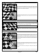
+ Only the bottom of the hinge gap needs to be sealed. It is not necessary to seal both the bottom and the top. q Disconnect the clevis from one elevon control horn, so that the elevon can be deflected fully in both directions. q Remove the protective backing from the covering material. With the elevon fully deflected in the 'UP' position, place the length of covering material over the hinge line (on the bottom), making sure that the crease is pushed completely down into the hinge line.
PREFLIGHT CHECK AND SAFETY l Completely charge the transmitter and receiver batteries before your first day of flying. Check every bolt and every glue joint in the aircraft to ensure that everything is tight and well-bonded. This should include all of the control surface hinges as well. l l Double-check that you've installed and tightened all of the servo horn retaining screws. Double-check that the receiver, ESC and flight battery are properly secured into place.
THIS PAGE INTENTIONALLY LEFT BLANK Page 18
PRODUCT EVALUATION SHEET Telling us what you like and don't like determines what model kits we make and how we make them. We would appreciate it if you would take a few minutes of your time to answer the following questions about this kit and your modeling interests. Simply fold this form on the dotted lines, seal with tape and mail it to us. Do not use staples and make sure our address faces out. Global Hobby Distributors will not disclose the information it collects to outside parties.
Fold along dotted line ______________________________ ______________________________ ______________________________ Post Office will not deliver without proper postage (Return Address Here) Global Hobby Distributors Attn: Global Services 18480 Bandilier Circle Fountain Valley CA 92728-8610 Fold along dotted line Page 20