
Instruction manual


MOUNTING THE HULL
Before continuing with additional work it is best to
mount the hull. Doing this step will help prevent
details from becoming damaged while you handle
the model. It will also allow you to make any align-
ments that require a true waterline. So, proper
mounting of the hull is very important. While any
modeler can devise his own mounting, this kit con-
tains a building-ways mounting system. A second
option, which can be purchased separately, is a
mounting board with two brass, or wooden,
pedestals.
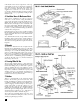
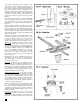
1. Building-Ways
The building-ways mounting system is mostly suit-
able for models without sails. The one contained in
the kit is similar to the actual building-ways used for
constructing the
Pride of Baltimore II at Baltimore,
Maryland’s Inner Harbor.
You must drill the keel of the model in order to apply
the rods that anchor the model to the ways. The
building-ways are easily assembled, consisting pri-
marily of 3/16” square stock, representing square
timbers (see figure 30 for actual construction). The
ways should be mounted on a baseboard sized
approximately 24” x 9”. The board must be pur-
chased separately, or you may make your own.
Expanding the size of the board will allow you to cre-
ate a mini-diorama comprised of boat yard ground
activity. At Inner Harbor, the lowest wide timbers
were set directly on the ground.
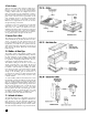
2. Mounting Board with Two Pedestals
As an option, you can purchase two brass or wooden
pedestals. You will need a 1” long and a 1-3/8” long
pedestal, or any length with one about 3/8” longer
than the other. If you own a router, or can borrow
one, you will be able to cut a nice fancy edge on the
baseboard if you do not purchase one commercially.
Finish the base with a dark stain or paint.
If you decide to use the mounting board and
pedestals, drill pilot holes in the keel and screw holes
in the mounting board. Locate the pedestals so the
load waterline is parallel to the mounting board. Plan
sheet 3 shows the approximate location of the two
optional pedestals. If something went awry and the
balance is off, add a brass shim under one pedestal to
correct it.
If you intend to put the model in a glass or plastic
case, you could let the bottom of the case serve as a
baseboard.
Note
: It is recommended that either choice mounting
piece be finished before mounting the Hull Assembly
into place.
21
STAGE D
ADDING THE HULL DETAILS
1. Locating Deck Fittings & Structures
If you included the coamings when planking the
deck, you at least have those structures located. Now
it is time to locate all the other items that must be
added: on the deck, inside bulwarks, and top of the
rail; this includes items such as fife rails, bitts, wind
-
lass, deck prisms, binnacle, watertight steel hatch,
steering wheel box, ship’s boat cradles, ventilator
boxes, mushroom vents, fire hydrants, bilge pumps,
pin rails and belaying pin holes in the rail, eyebolts,
cleats, catheads, lifelines and stanchions, swivel
guns, and deck lockers. Outboard, you will locate the
propeller struts, shaft log, channels, and eyebolts for
bowsprit rigging, rudder preventer chains, and rud-
der pintles and gudgeons.
To locate items, measure from some known “bench
mark” such as the center of a mast, the centerline, or
outboard from the keel/sternpost intersection. The
centerline has those two wide deck planks so it is
easy to find. Mark all items lightly in pencil.
Fittings such as eyebolts and cleats associated mostly
with rigging can wait until later. However, it is not a
bad idea to get all these fittings installed while work-
ing on the deck. Get them done, then clean up and
varnish the deck. Afterward, when you start the rig-
ging, you will be glad all those fittings are ready.
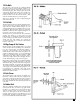
2. Bow Fairlead
Make the fairlead at the bow from wood and drill the
five holes for lines leading toward the bow pin rail
platform. Paint the fairlead black.
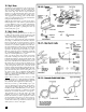
3. Cabin Trunks
The crew berthing access trunk, main salon trunk,
engine room trunk, and after cabin trunk are all sim-
ilar in general construction, but the companionways,
skylights, and other top details vary on each trunk.
Follow the plans carefully and do not make any
assumptions that one item looks like another.
The basic box for each trunk should be made from
3/64”-thick basswood. You could also use a solid
block. The kit contains a chunk of basswood for this
purpose (see figure 31 for the basic structure and how
it fits upon the deck coamings). If you did not install
coamings while installing the deck planking, the fig-
ure also shows the detail which must be made now.
The top of the main salon trunk and the after cabin
trunk must be planked. The outboard wide plank
and the fore and aft end planks on the real ship are
mahogany, so on the model, they should be
mahogany in color. The top planking within these
planks on the real ship looks exactly like the main
deck planking. It is Douglas fir with a weathered
grey look, and you can see the caulking seams. The
other trunks have all mahogany tops. With so many
fixtures attached, you could use solid sheet wood for
the top on the model.
All of the companionways, skylights, etc. can be
made and just glued on the tops of the trunks. If you
want to have any one of the companionways, or
hinged covers open, you must cut out an opening in
the top and do some detailing below.
STAGE E