
Installation manual

PART 12: TROUBLESHOOTING (CONTINUED)
Table 12-2: 926 Control Board FAULT Codes
Code Description Remedy
F00
High Temperature Limit
Exceeded.
1. Check circulation pump operation
2. Assure that there is adequate flow through the boiler by accessing the status menu and assuring that there is
less than a 50°F rise from the return thermistor to the supply thermistor.
3. Check thermistor reading on supply thermistor. Replace switch if faulty.
4. Disconnect the two wires from the thermostat terminals and connect the wires together. Depress the S4/Reset
button. If the fault clears, the problem is outside the boiler
F01
ECO circuit 2
Vent temperature
High Gas Pressure (if
equipped)
Low gas pressure (if
equipped)
Low Level (if equipped
with UL353 LWCO)
1. If the boiler is equipped with High and/or Low gas pressure switches, examine the switch(es) to see if the yel-
low LED is illuminated on the switch. If so, correct the gas supply problem associated with the switch and reset
the switch by pressing on the cover of the switch over the red button to reset the switch. Pressing the button
requires a firm push. Push the Reset button on the front panel of the boiler to reset the boiler control.
2. If the boiler has a UL353 LWCO, check to see if the red LED on the LWCO control box is illuminated. If so, cor-
rect the low water condition and press the reset button on the LWCO control box to reset the LWCO. The LED
should change to green. Press the reset button on the front panel of the boiler to reset the boiler control.
3. Check the flue for obstructions or any sign of damage especially signs of excessive heat. Repair as necessary.
Push red reset button on flue temperature switch located on the flue inside the rear access door of the boiler.
NOTE: Switch temperature must be less than 90°F to reset. Run the boiler and check the flue temperature. If
the flue temperature is within specs and the switch trips, replace the switch. If the flue temperature is excessive
check and adjust combustion controls on the boiler. If problem persists, inspect the target wall in the combus-
tion chamber and replace it if cracked or damaged.
F02
Interrupted or Shorted
Supply (Outlet)
Thermistor.
1. Check the electrical connection to the thermistor on the outlet manifold. Verify 5 VDC by checking in Molex
connector. If no 5 VDC, check harness. If harness is OK, replace control. NOTE: Boiler will reset automatically.
Verify thermistor values by referencing chart in this manual.
2. Replace thermistor if necessary.
F03
Interrupted or Shorted
Return (Inlet) Thermistor.
1. Check the electrical connection to the thermistor on the inlet manifold. Verify 5 VDC by checking in Molex
connector. If no 5 VDC, check harness. If harness is OK, replace control. NOTE: Boiler will reset automatically.
Verify thermistor values by referencing chart in this manual.
2. Replace thermistor if necessary.
F05
Supply (Outlet)
Temperature exceeds
230°F.
1. Check circulation pump operation.
2. Assure that there is adequate flow through the boiler by accessing the status menu and assuring that there is
less than a 50°F rise from the return thermistor to the supply thermistor.
3. Troubleshoot thermistor by following steps in |F02|
F06
Return (Inlet) Temperature
Exceeded 230°F.
1. Check circulation pump operation.
2. Assure that there is adequate flow through the boiler by accessing the status menu and assuring that there is
less than a 50°F rise from the return thermistor to the supply thermistor.
3. Check direction of flow on boiler circulator. (See Piping Details in this manual.)
4. Troubleshoot thermistor by following steps in |F02|
F09
No flame detected – The
boiler will make three at-
tempts at ignition before
the control goes into this
lockout condition.
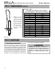
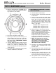
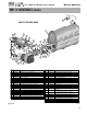
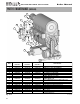
1. Watch the igniter through the observation window provided.
2. If there is no spark, check the spark electrode for the proper ¼” gap. Use 2 quarters together as a gauge to
hold ignitor against to check gap distance. (See Fig. 12-3 in manual)
3. Remove any corrosion from the spark electrode and flame rectifier probe.
4. If there is a spark but no flame, check the gas supply to the boiler.
5. If there is a flame, check the flame sensor.
6. Check any flue blockage or condensate blocks.
F10
Loss of Flame Signal –
The boiler will relight 4
times before the control
goes into this lockout
condition – Will reset
automatically in 1 hour.
1. Monitor the gas pressure to the unit while in operation.
2. Assure that the flame is stable when lit.
3. Check to see if the green light on the display module is out while the boiler is running.
4. If the green light doesn’t come on or goes off during operation check the flame signal on the status menu.
5. If the signal reads less than 1 microampere, clean the flame rectifier probe.
6. If the flame rectifier probe continues to read low, replace it.
7. Check the stability of the flame rectification signal. If the signal is unstable, you may need to replace the burn-
er gasket.
F11
False Flame Signal – The
boiler will lock out if it
senses a flame signal
when there should be
none present.
1. Look into window. If there is flame, turn the gas off to the unit at the service valve and replace gas valve.
2. If the flame signal is present and there is no flame, replace the flame rectification probe.
3. If the flame signal is not present after turning off the gas supply, check the gas valve electrical connection.
4. Remove the valve and check for obstruction in the valve seat or replace the gas valve.
5. Turn the gas on at the service valve after corrective action is taken.
6. Check for condensate back up. Condensate back up can damage the refractory wall, and if the wall falls
against the rectifier probe, it may conduct the signal to ground, giving a false reading.
F13
Combustion Fan Speed
too low or high – Boiler
will lock out if it senses
fan speed is less than
70% or greater than 130%
of its expected rate for
more than 60 seconds.
1. Check the combustion air fan wiring.
1a. Check the 24 VAC signal by measuring from any connected safety to ground. A low voltage situation may
cause a “false” error code
2. Replace the combustion air fan.
3. Replace the control board.
F20
Condensate cup is full.
1. Check condensate lines for obstructions
2. Check float switch in condensate reservoir.
3. Check wiring from condensate reservoir to 926 control and repair as necessary
PP
Parameters Programmed Press S4 reset for at least 1 second.
F31
Program Parameter Error Control must be re-programmed. If programming does not solve problem, control must be replaced.
GAS-FIRED HOT WATER SUPPLY BOILER Boiler Manual
62