
Installation manual


to normal operation. If the code is entered cor-
rectly, the control will switch off the gas valve and
purge fan while showing a solid |
---
| in the dis-
play. The display will then show a |1| alternating to
|dd|. This first function verifies that the control is
configured as a VWH boiler.
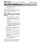
C. PROGRAM NAVIGATION
Next you will have to press the {S/3} key to move
through each function. To increase or decrease
a value, you will need to press either the {S/1
-
}
key or {S/2+} key to change the default values. If
there is no key action for 1 minute, the display
returns to normal operation. Changes are effec-
tive immediately but not directly stored until the
{S/4} key is pressed down for 3 seconds then the
new values are stored. Listed below are the vari-
ety of functions the installer can program into
the 926 Control.
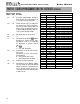
Function Default Function
Number Value Description
1 dd No change allowed
2 149ºF No change allowed
3 180˚ Maximum Domestic water heater
delivery temperature allowed in
user menu. Installer can set the
maximum temperature. Range
95-185
4 20ºF Offset temperature / number of
degrees above the tank set point
that will control the boiler output.
Ex. Storage tank set at 120º with
20º offset boiler supply will be
140º. Range 1-39
5 7ºF Allows the installer to change the
differential temperature (dh)
Range 1-18
6 5 Min. Circulator Post Purge Time after
tank sensor is satisfied that the
pump will run (Note: it is recom-
mend that Circulator Post Purge
Time be set no greater than 5 min-
utes). Range: 0 to 10 minutes
Function Default Function
Number Value Description
7 68 N/A (No change required)
8 5 N/A (No change required)
9 180 N/A (No change required)
10 68 N/A (No change required)
11 95 N/A (No change required)
12 68 N/A (No change required)
13 0 N/A (No change required)
14 30 N/A (No change required)
15 0 Bus Addressing Boilers (Cascade
8 Boiler Max.)
Master = Address 0 / Followers =
Address 1 thru 7.
Note: Never address boiler with
number 8 which is not to be used.
Range: 0-8
16 0 Allows the installer to connect up
a 0-10 Volt signal directly from
Building Management System. To
activate, change value to 2.
Warning: Values 1 and 3 are not to
be programmed into board
Range: 0-3
17 0 N/A (No change required)
18 1 N/A (No change required)
19 180 N/A (No change required)
20 2 Flow switch. Do not change
0= none
1=water pressure switch
2=flow switch
3=low water cut-off
21 0 N/A (No change required)
22 100% Maximum boiler output percent-
age. Default = 100%. This param-
eter can be adjusted to lower the
maximum boiler output if neces-
sary. Example MOD CON 500
boiler setting at 80% boiler will go
to 400000 BTU/hr max rather than
500000 BTU/hr. Range 50–100%
PART 11: START-UP PROCEDURES FOR THE INSTALLER (CONTINUED)
CAUTION
The Boiler cannot be programmed while
there is a call for heat.
GAS-FIRED HOT WATER SUPPLY BOILER Boiler Manual
58