
Installation manual

PART 7: GAS PIPING (CONTINUED)
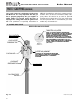
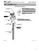
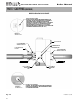
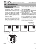
D. CHECK INLET GAS PRESSURE
The Gas Valve is equipped with an Inlet Gas
Pressure Tap that can be used to measure the
gas pressure to the unit. To check Gas Pressure
perform the steps listed below:
1. Before you connect to the inlet pressure you
must shut off the gas and electrical power to
unit.
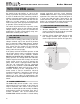
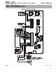
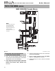
2 Loosen the pressure tap with a small
screwdriver. Refer to Figures 7-2, 7-3 and 7-4
for location.
3. Each unit is equipped with a needle valve
that will accept a 5/16 ID hose to connect to
a digital manometer or liquid gauge to
measure incoming pressure from 0-35” w.c.
4. Turn on the Gas and Power up the unit.
5. Put the unit into manual service mode
(Details on service mode in back of this
manual). In service mode, monitor pressure
to assure it does not drop below 1 inch from
its idle reading. If Gas Pressure is out of range
or pressure drop is excessive, contact the gas
utility, gas supplier, qualified installer or
service agency to determine correct action
that is needed to provide proper gas pressure
to the unit. If Gas Pressure is within normal
range proceed to Step 6.
6. Exit Service mode, then turn power off and
shut off gas supply at the manual gas valve
before disconnecting the hose from the gas
monitoring device. Tighten the screw on the
pressure tap tightly and turn gas on and
checks for leaks with soapy solution.
It is recommended that a soapy solution be used
to detect leaks. Bubbles will appear on the pipe
to indicate a leak is present. The gas piping must
be sized for the proper flow and length of pipe,
to avoid pressure drop. Both the gas meter and
the gas regulator must be properly sized for the
total gas load. If you experience a pressure drop
greater than 1" w.c. (.87 kPa), the meter, regula-
tor or gas line is undersized or in need of serv-
ice. You can attach a manometer to the incom-
ing gas drip leg, by removing the cap and
installing the manometer. The gas pressure
must remain between 3.5" (.87 kPa) and 14" (3.5
kPa) during stand-by (static) mode and while in
operating (dynamic) mode. If an in-line regula-
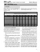
NATURAL GAS SUPPLY PIPING CAPACITY CHART
(0.6 specific gravity gas; 0.5” WC pressure drop)
*Schedule 40 iron pipe size in nominal inch size
Boiler Model 1 Boiler 2 Boilers 3 Boilers 4 Boilers 5 Boilers 6 Boilers 7 Boilers 8 Boilers
Cubic Ft. Hr. 300 600 900 1200 1500 1800 2100 2400
ModCon 300 VWH @ 100’ of pipe 1 1/4” 1 1/2” 2” 2 1/2” 2 1/2” 2 1/2” 3” 3”
ModCon 300 VWH @ 250’ of pipe 1 1/2” 2” 2 1/2” 3” 3” 3” 4” 4”
Boiler Model 1 Boiler 2 Boilers 3 Boilers 4 Boilers 5 Boilers 6 Boilers 7 Boilers 8 Boilers
Cubic Ft. Hr. 500 1000 1500 2000 2500 3000 3500 4000
ModCon 500 VWH @ 100’ of pipe 1 1/2” 2” 2 1/2” 3” 3” 3” 4” 4”
ModCon 500 VWH @ 250’ of pipe 2” 2 1/2” 3” 3” 4” 4” 4” 4”
Boiler Model 1 Boiler 2 Boilers 3 Boilers 4 Boilers 5 Boilers 6 Boilers 7 Boilers 8 Boilers
Cubic Ft. Hr. 850 1700 2550 3400 4250 5100 5950 6800
ModCon 850 VWH @ 100’ of pipe 2” 2 1/2” 3” 4” 4” 4” 4” 5”
ModCon 850 VWH @ 250’ of pipe 2 1/2” 3” 4” 4” 5” 5” 5” 5”
Table 7-1
C. GAS TABLE
Refer to Table 7-1 to size the supply piping to
minimize pressure drop between meter or
regulator and unit.
Maximum Capacity of Pipe in Cubic Feet of Gas
per Hour for Gas Pressures of 0.5 w.c. or Less and
a Pressure Drop of 0.3 Inch w.c.
GAS-FIRED HOT WATER SUPPLY BOILER Boiler Manual
40