
Installation manual
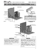
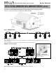
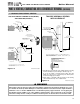
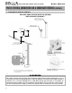
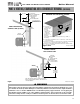

Figure 6-9 LP-205-G Rev. 6/23/08
J. DIAGRAM FOR VERTICAL VENTING
0,1
0,1
:+,&+(9(5,6*5($7(5
29(50$;,080
612:/(9(/25
,17$.($,5
9(17
(;+$867
9(17
5,*+76,'(9,(:
7((
675$,*+7
&283/,1*
(;7(5,25:$//
,16(57,1/(7(;+$867
6&5((13529,'(',172
675$,*+7&283/,1*
,16(57,1/(7(;+$867
6&5((163529,'(',172
($&+(1'2)7((
127(9(170867%($7/($6729(50$;,080612:
/(9(/25:+,&+(9(5,6*5($7(5&+(&.:,7+/2&$/
&2'(5(48,5(0(176
TWO PIPE ROOF VENTING WITH TEE (INTAKE)
AND COUPLING (EXHAUST)
PART 6: VENTING, COMBUSTION AIR & CONDENSATE REMOVAL (CONTINUED)
n
WARNING
All vent pipes must be glued, properly supported and the exhaust must be pitched a minimum of a ¼" per
foot back to the heater (to allow drainage of condensate). Exhaust connection insertion depth should be a
minimum of 2½” for models 300/500 and 3” for 850. When placing support brackets on vent piping, the
first bracket must be within 1 foot of the appliance and the balance at 4 foot intervals on the vent pipe.
The boiler venting must be readily accessible for visual inspection for the first three feet from the boiler.
GAS-FIRED HOT WATER SUPPLY BOILER Boiler Manual
37
Fig. 6-10 Multiple Concentric Vent
Spacing – Vertical
Fig. 6-11 Multiple Concentric Vent
Spacing – Horizontal