
Installation manual


0,1
0,1
327(17,$/612:/(9(/
25
$%29(0$;
5,*+76,'(9,(:
(;+$867
9(17
$,5,17$.(
9(17
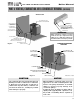
6833257%5$&.(76
0867%(86('21
$//+25,=217$/
$1'9(57,&$/3,3,1*
7((
675$,*+7
&283/,1*
7239,(:
0$;
(;+$867
9(17
$,5,17$.(
9(17
7((
675$,*+7
&283/,1*
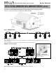
,1/(7(;+$867
6&5((1
,16(57,1/(7(;+$867
6&5((163529,'(',172
($&+(1'2)7((
,16(57,1/(7(;+$867
6&5((13529,'(',172
675$,*+7&283/,1*
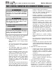
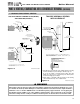
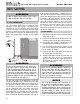
127(9(170867%($7/($6729(50$;,080612:
/(9(/25:+,&+(9(5,6*5($7(5&+(&.:,7+/2&$/
&2'(5(48,5(0(176
Figure 6-7 LP-205-E Rev. 6/23/08
Figure 6-8 LP-205-F Rev. 5/15/08
POTENTIAL SNOW LEVEL
7' OR 1'
ABOVE MAX.
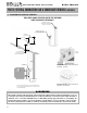
NOTE: VENT MUST BE AT LEAST 12" OVER MAXIMUM SNOW
LEVEL OR 24" WHICHEVER IS GREATER - CHECK WITH LOCAL
CODE REQUIREMENTS
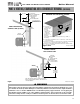
VENT
ALL HORIZONTAL
AND VERTICAL PIPING
INTAKE AIR
RIGHT SIDE VIEW
EXHAUST
VENT
SUPPORT BRACKETS
MUST BE USED ON
VENT KIT
(SEE CHART)
PART 6: VENTING, COMBUSTION AIR & CONDENSATE REMOVAL (CONTINUED)
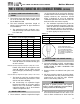
NOTE: THE EXHAUST VENT
CONNECTION MUST BE INSERTED A
MINIMUM OF 2-1/2"
FOR THE MODCON 300/500
AND 3" FOR THE MODCON 850
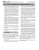
1. Prep PVC Pipe by removing burrs on the leading edge before inserting
into the boiler adapter to prevent damage to internal o-ring seal.
Do not use any Liquids or Petroleum based products that could
damage the o-ring seal - It is recommended you use talcum powder
to assist in inserting pipe into adapter.
2. Tighten clamp to a maximum of 50 inch pounds to avoid reforming
connected PVC which may cause combustion leaks.
I. DIAGRAMS FOR SIDEWALL VENTING
TWO PIPE SIDEWALL VENTING W/TEE (INTAKE)
AND COUPLING (EXHAUST)
TWO PIPE SIDEWALL VENTING
WITH V-SERIES KIT
n
WARNING
All vent pipes must be glued, properly supported and the exhaust must be pitched a minimum of a ¼" per
foot back to the heater (to allow drainage of condensate). Exhaust connection insertion depth should be a
minimum of 2½” for models 300/500 and 3” for 850. When placing support brackets on vent piping, the
first bracket must be within 1 foot of the appliance and the balance at 4 foot intervals on the vent pipe.
The boiler venting must be readily accessible for visual inspection for the first three feet from the boiler.
GAS-FIRED HOT WATER SUPPLY BOILER Boiler Manual
36