
Installation manual
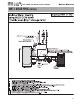
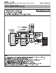
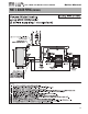
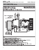
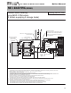
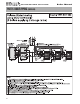
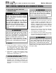

Volume Water Heating
using MOD CON boilers
(2 boilers supplying 2 storage tanks)
Drawing VWH 2/2 V MC
flow switch
constant
circulation
flow switch
condensate
drainage
MOD
CON
MOD CON 2
MOD
CON
MOD CON 1
master
address = 0
follower
address = 1
recirculation line
hot water supply
cold water
ASEE 1017 rated anti-scald valve
(recommended)
expansion
tank
vacuum breaker
(where required by code)
Superstor Ultra
coil booster tank
Superstor Ultra
coil booster tank
mechanical aquastat
(both tanks)
wired in series
(preferred)
required
system/
pipe
sensor
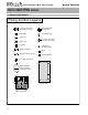
System/Pipe Sensor
Used if sensor cannot be placed at tank –
(Important to note that Pumps must be
wired to run continuously to operate in
this configuration)
NOTES:
1. This drawing is meant to show system piping concept only. Installer is responsible for all equipment & detailing required by local codes.
2. Boiler circulator must be rated for open loop application. Do not use cast-iron circulators
3. Boiler circulator(s) operate continuously
4. The minimum pipe size for connecting to a water storage tank is 1.5 inch.
5. The minimum pipe size for connecting a MOD CON boiler is 1.5 inches for MOD CON 300 VWH, and 2-inches for MOD CON 500 & 800
6. All pumps are shown with isolation flanges or full port ball valves for isolation. The alternative is standard flanges
with full port ball valves and a separate flow check valve.
7. Install a minimum of 12 diameters of straight pipe upstream of all circulators and check valves.
8. Install vacuum relief valve in accordance with local code requirements
9. All multiple boilers and multiple storage tanks shall be installed with reverse return piping as shown
10. Anti-scald rated mixing valve is recommended on all tanks if the leaving hot water temperature from tank is above 119 °F.
11. Expansion tank must be rated for use with potable water
12. Use either a mechanical aquastat in each tank wired in series or system/pipe sensor shown. (Do not use both.)
13. Tank aquastats or pipe sensor connected to DHW sensor terminals on boiler addressed as #1.
14. The system/pipe sensor must be placed on common piping to the tank, as close to tank as possible.
15. The system/pipe sensor is wired to the system/pipe sensor terminals on the master boiler.
PART 5: BOILER PIPING (CONTINUED)
GAS-FIRED HOT WATER SUPPLY BOILER Boiler Manual
26