
Installation manual

GAS-FIRED HOT WATER SUPPLY BOILER Boiler Manual
19
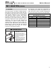
PART 5: BOILER PIPING (CONTINUED)
LP-205-E Rev. 12/5/07
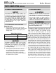
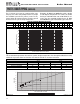
Figure 5-2
FRICTION IN FEET OF HEAD
0
10
20
30
40
50
60
70
80
90
2 4 6 8 10 12 14 16 18 20 22 24 26 28 30 32 34 36
FRICTION IN FEET OF HEAD
FLOW OF GPM
MODCON 300 MODCON 500
MODCON 850
MOD CON HEAT EXCHANGER PRESSURE DROP
0
1
2
3
4
5
6
7
0 100 200 300 400 500 600 700 800
Combined Boiler Water Flow (GPM)
Pipe Diameter Size (Inches)
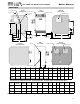
Multiple Boiler Manifold Piping
MULTIPLE BOILER MANIFOLD PIPING
Flow rate 30 50 60 85 90 100 120 150 170 180 200 210 240 250 255 300 340 350 400 425 510 595 680
Pipe Dia. 2” 2½” 2½” 3” 3” 3” 4” 4” 4” 4” 4” 4” 5” 5” 5” 5” 5” 5” 5” 5” 6” 6” 6”
SYSTEM TEMPERATURE RISE CHART
20°Δt 25°Δt
Model Friction Feet Flow G P M Friction Feet Flow G P M
Mod Con 300 VWH 19’ 30 12’ 24
Mod Con 500 VWH 19’ 50 11’ 40
Mod Con 850 VWH 35’ 85 26’ 65
The chart below represents the various system design temperature rise through the Mod Con along
with their respective flows and friction loss which will aid in circulator selection.
Example: (5) Mod Con 300 Boilers with a design
of 30 degree temperature rise with each boiler
having an individual flow rate of 20 GPM. To cor-
rectly size the manifold feeding these (5) Mod
Con 300 Boilers you would need a pipe size of 3”.
Fig. 5-1 below represents the combined flow rates
and pipe sizes when using multiple boilers to design
the manifold system for the primary circuit. To size,
simply add up the number of boilers and the required
flow rates for the system design temperature.
Figure 5-1