
Specifications

55
LP- 276 REV. 9.4.14
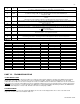
|d4| — Not used.
|d5| — Not used.
|d6| — Actual fan speed multiplied by 10 (Example: If fan speed displayed is |410| RPM x 10 = 4100 actual fan speed)
|d7| — Actual ionization current read from flame rectification probe
|d8| — 0 (not used).
|d9| — Circulator pump - Off = |0|, On = |1|.
|d10| — Actual status of bus communication |co| = connected, |nc| = not connected
|d11| — Storage tank set point
|d12| — Power on hours in thousands (display will not read until 100 hrs). Example: Display number x 1000 = Power on hours.
|d13| — Not used.
|d14| — Total running hours of boilers in thousands (display will not read until 100 hrs.)
|d15| — Passed ignition attempts in thousands (display will not read until 100 ignition attempts).
Example: Display number x 1000 = ignition attempts. Display showing 12.3 x 1000 = 12300 ignition attempts.
|d16| — This function only becomes active when boiler is set as the Master. It allows the user to monitor the system pump connected to
the Master Boiler (0 = Off, 1 = On) in a multiple boiler installation. Each boiler firing output percentage is displayed.
|P0| - Master Boiler - Alternating (0-100 Percentage firing rate)
|P1| - Follower Boiler #1 – Alternating (0-100 Percentage firing rate)
|P2| - Follower Boiler #2 – Alternating (0-100 Percentage firing rate)
|P3| - Follower Boiler #3 – Alternating (0-100 Percentage firing rate)
|P4| - Follower Boiler #4 – Alternating (0-100 Percentage firing rate)
|P5| - Follower Boiler #5 – Alternating (0-100 Percentage firing rate)
|P6| - Follower Boiler #6 – Alternating (0-100 Percentage firing rate)
|P7| - Follower Boiler #7 – Alternating (0-100 Percentage firing rate
NOTE: If you toggle beyond parameters of connected boilers, the display will go into the next function value.
D. TEST MODE
This function is intended to simplify the gas valve adjustment. Listed below are the recommended limits on each VWH boiler and
combustion settings. Automatic modulation does not take place when the controller is in test mode, only temperature limitation based
on the VWH boiler central heating set point. The user can increase or decrease the fan speed by pressing either {S1/-} or {S2/+}.
To activate test mode, press the {S2/+} and {S3/Program} keys together for 1 second. Once activated, you will see in the display {Ser}
and the actual fan speed. The measurement of the combustion levels should always be taken at the highest and lowest fan speeds.
After 20 minutes, test mode stops automatically. To exit test mode, press {S1/-} and {S2/+} together for 1 second.
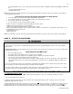
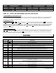
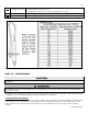
COMBUSTION SETTINGS ON ALL MODELS
Natural Gas
Propane LP
Fan Speed
low
high
low
High
Carbon Monoxide (CO%)
0 – 20 ppm
70 – 135 ppm
0 – 20 ppm
80 – 150 ppm
Carbon Dioxide (CO
2
%)
8 ½ - 9 ½%
8 ½ - 9 ½%
9 ½ - 10 ½%
9 ½ - 10 ½%
Table 15 – Combustion Settings on All Models