
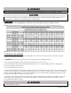
Specifications


48
LP- 276 REV. 9.4.14
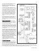
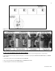
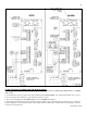
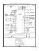
Figure 27 – Mod Con VWH Cascade Master and Follower
N. VWH CASCADE FOLLOWER PUMP AND SENSOR WIRING
1. If it is desired to have the boiler control the boiler pump, connect the boiler pump to the BOILER HOT, BOILER NEUT, and BOILER
GND terminals.
2. Connect the tank sensor(s) or return sensor to the terminals marked TANK SENSOR on the follower boiler addressed as 1. There
are no connections to these terminals on other follower boilers in the system.
3. Do not connect anything to the OUTDOOR SENS, 0-10V, or THERMOSTAT terminals.
4. If it is desired to monitor the boiler system to detect a lockout condition, a dry contact alarm relay is provided. Please see Figure 27
for wiring suggestions for this relay. Note that the alarm output of the boiler addressed as 1 will be active for lockout alarms on boiler 1
as well as on the master boiler.