
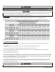
Specifications


47
LP- 276 REV. 9.4.14
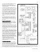
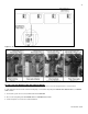
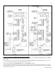
Figure 25 – LP-205-JJ
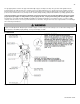
Figure 26 – Cascade Resistor Plug Installation Detail
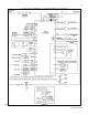
M. VWH CASCADE MASTER PUMP AND SENSOR WIRING
1. Place the cascade master overlay sticker onto the field connection board on the boiler designated as the cascade master.
2. If it is desired to have the boiler control the boiler pump, connect the boiler pump to the BOILER HOT, BOILER NEUT, and BOILER
GND terminals.
3. Connect the system sensor to the terminals marked SYS SENSOR.
4. Do not connect anything to the OUTDOOR SENS or THERMOSTAT terminals.
5. If 0-10 volt input is used, connect to marked terminals.