
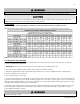
Specifications


46
LP- 276 REV. 9.4.14
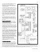
F. LOW VOLTAGE CONNECTIONS FOR STANDARD BOILER
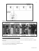
All low voltage cables should enter the electrical junction box through the provided knock out holes shown in Figure 23. Connect all low
voltage field devices in the low voltage terminal strip located in the electrical junction box (shown in Figure 24).
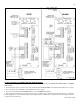
G. TANK SENSOR OR MECHANICAL CONTROL
Connect the tank sensor or mechanical controls to the TANK SENSOR terminals of the low voltage terminal strip show in Figure 24.
The control will automatically determine which type of sensor is connected and will operate accordingly. Caution should be used to
ensure that neither of these terminals becomes connected to ground.
H. SYSTEM / PIPE SENSOR
The system/pipe sensor can be used to control the temperature of the storage tank when a tank sensor or mechanical control cannot
be mounted. The system/pipe sensor must be wired into the terminals of the low voltage terminal strip as shown in Figure 24. It is
important to note that when a system/pipe sensor is used, the circulating pump must be wired to operate continuously. Failure to do so
will short cycle the boiler.
The system/pipe sensor can also be used in a cascade system when the sensor is placed on the supply line of multiple boilers that feed
the storage tank. This will control the temperature and modulate the firing rate of the connected boilers. The system/pipe sensor would
then be wired into the master boiler terminals on the low voltage strip as shown in Figure 24.
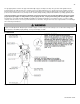
I. OPTIONAL HIGH GAS PRESSURE SWITCH
1. If an optional high gas pressure switch is used, it should be installed on the outlet side of the gas valve. This is normally closed and
will open if the pressure goes above 1.5” w.c. on the outlet side.
2. Locate the two pigtails hanging from the electrical box inside of the boiler cabinet. Remove and discard the jumper plug from one of
the unused pigtails.
3. Connect the high gas pressure switch to the pigtail that you removed the jumper plug from.
J. OPTIONAL LOW GAS PRESSURE SWITCH
1. If an optional low gas pressure switch is used, it should be installed on the inlet side of the gas valve. This is normally closed and will
open if the pressure goes below 1” w.c. on the inlet side.
2. Locate the two pigtails hanging from the electrical box inside of the boiler cabinet. Remove and discard the jumper plug from one of
the unused pigtails.
3. Connect the low gas pressure switch to the pigtail that you removed the jumper plug from.
K. FLOW SWITCH
This VWH boiler requires the use of a flow switch. The flow switch kit 7350P-605 or 7350P-606 comes packaged with detailed
installation instructions which should be read and followed to ensure a functional system.
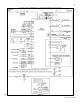
L. WIRING OF THE CASCADE SYSTEM COMMUNICATION BUS
1. A Cascade Bus Termination Plug has been installed on the customer connection board of this boiler. The purpose of this plug is to
stabilize communication between multiple boilers and reduce electrical “noise”. See Figures 26 and 27 for Cascade Bus Termination
Plug installation detail.
2. Use standard CAT3 or CAT5 computer network patch cables to connect the communication bus between each of the boilers. These
cables are readily available at any office supply, computer, electronic, department or discount home supply store in varying lengths. If
you possess the skills you can also construct custom length cables.
3. It is recommended to use the shortest length cable that will reach between the boilers and create a neat installation. Do not run
unprotected cables across the floor where they may become wet or damaged. Avoid running communication cables parallel and close
to or against high voltage (120 volt or greater) wiring. HTP recommends that the maximum length of communication bus cables not
exceed 200 feet.
4. Route the communication cables through one of the knockouts in the cabinet.
5. Connect the boilers in a daisy chain configuration as shown below. It is best to wire the boilers using the shortest wire runs rather
than trying to wire them in the order that they are addressed. The communication bus jacks on the customer connection panel are
interchangeable so you can use either one or both in any order to connect the cable.
If you have connected the boilers to each other properly, there will be no open communication connection ports.