
Specifications


34
LP- 276 REV. 9.4.14
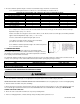
2. The total combined equivalent length of exhaust vent and intake air pipe should not exceed 200 feet.
a. The equivalent length of friction loss in elbows, tees, and other fittings are listed in Table 11.
FRICTION LOSS EQUIVALENT FOR STAINLESS OR PLASTIC PIPING AND FITTINGS
FITTING DESCRIPTION
4”
6”
8”
90
o
elbow short radius
3’
3’
3’
90
o
elbow long radius
2’
2’
2’
45
o
elbow
1’
1’
1’
Coupling
0’
0’
0’
Tee (intake only)
0’
0’
0’
V Series Vent Kit
1’
1’
1’
AL20 4C Vent Terminal
1’
1’
1’
Pipe (All Materials)
1’
1’
1’
Table 11 – Friction Loss in Equivalent Feet - *Friction loss for long radius elbow is 1’ less.
b. For example: If the exhaust vent has two short 90
o
elbows and 10 feet of PVC pipe we will calculate: Exhaust Vent Pipe
Equivalent Length = (2x3) + 10 = 16 feet.
Further, if the intake air vent pipe has two short 90
o
elbows, one 45
o
elbow, and 10 feet of PVC pipe, the following calculation
applies: Intake Air Equivalent Length = (2x3) + 1 + 10 = 17 feet.
Therefore, total combined equivalent length equals 33 feet.
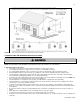
c. The intake air vent pipe and the exhaust vent are intended to
penetrate the same wall or roof of the building.
d. The minimum combined equivalent length is 32 combined equivalent
feet – 16 ft intake and 16 ft. exhaust.
F. LONGER VENT RUNS
The maximum combined equivalent length can be extended by equally
increasing the diameter of both the exhaust and intake air vent pipes. However,
the transitions should begin a minimum of 32 combined equivalent feet from the
boiler equally on both the intake and exhaust.
The maximum equivalent length for increased diameter vent pipes is 275 feet, which includes the combined 32 feet from the boiler, 16
ft. (inlet) + 16 ft. (exhaust) = 32 ft. combined with transition total of 245 ft. upsize piping for longer vent runs.
VENT TRANSITION FITTING
SIZE
REDUCING COUPLING
FINAL VENT SIZE
4” Venting
6” x 4”
6”
6” Venting
8” x 6”
8”
Table 12 – Vent Transition Fitting
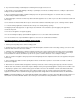
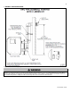
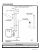
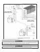
G. EXHAUST VENT AND INTAKE AIR PIPE INSTALLATION
All joints of positive pressure vent systems must be sealed completely to prevent leakage of flue products into living space.
1. Use only solid PVC or CPVC pipe, or a Polypropylene vent system, approved for use with Category IV boilers.
FOAM CORE PIPING IS NOT APPROVED FOR EXHAUST APPLICATIONS. Foam core piping may be used on air inlet piping only.
2. Remove all burrs and debris from joints and fittings.
3. When using PVC or CPVC pipe, all joints must be properly cleaned, primed, and cemented. Use only cement and primer approved
for use with the pipe material. Cement must conform to ASTM D2564 for PVC and ASTM F493 for CPVC pipe. NOTE: DO NOT
CEMENT POLYPROPYLENE PIPE.
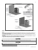
4. Ensure the vent is located where it will not be exposed to prevailing winds.
5. In all roof venting applications, exhaust discharge must point away from the pitch of the roof.
Figure 15