
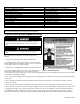
Specifications


18
LP- 276 REV. 9.4.14
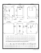
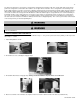
5. Feed green ground wire into boiler through the wire access.
6. From the front of the boiler, feed the ground wire up into the control box.
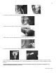
7. Once into the control box, attach the green ground to the ground bus connection.
8. Connect red wire from flow switch to boiler wire harness.
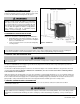
9. When installation is complete, power up the boiler and use the control to access installer parameter #20 and change the default
value to 2 (see Part 11 in this manual). When done, create a demand and observe boiler function to verify the installation is working
properly.
*Please note that these illustrations are meant to show system piping concept only. The installer is responsible for all
equipment and detailing required by local codes.