
Specifications


16
LP- 276 REV. 9.4.14
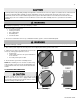
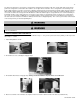
B. RELIEF VALVE
Connect discharge piping to a safe disposal location according to the following guidelines.
To avoid water damage or scalding due to relief valve operation:
• Discharge line must be connected to relief valve outlet and run to a safe place of disposal.
• Terminate the discharge line in a manner that will prevent possibility of severe burns or property damage should the relief
valve discharge.
• Discharge line must be as short as possible and the same size as the valve discharge connection throughout its entire length.
• Discharge line must pitch downward from the valve and terminate at least 6” above the floor drain, making discharge clearly
visible.
• Discharge line shall terminate plain, not threaded, with a material serviceable for temperatures of 375
o
F or greater.
• Do not pipe discharge to any location where freezing could occur.
• No shutoff valve may be installed between the relief valve and boiler or in the discharge line. Do not plug or place any
obstruction in the discharge line.
• Test the operation of the relief valve after filling and pressurizing the system by lifting the lever. Make sure the valve
discharges freely. If the valve fails to operate correctly, replace it with a new relief valve.
• Test relief valve at least once annually to ensure the waterway is clear. If valve does not operate, turn the boiler “off” and call
a plumber immediately.
• Take care whenever operating relief valve to avoid scalding injury or property damage.
• For boilers installed with only a pressure relief valve, the separate storage vessel must have a temperature and pressure relief
valve installed. This relief valve shall comply with Relief Valves for Hot Water Supply Systems, ANSI Z21.22 CSA4.4.
FAILURE TO COMPLY WITH THE ABOVE GUIDELINES COULD RESULT IN FAILURE OF RELIEF VALVE OPERATION,
RESULTING IN POSSIBILITY OF SUBSTANTIAL PROPERTY DAMAGE, SEVERE PERSONAL INJURY, OR DEATH.
C. SYSTEM WATER PIPING METHODS
EXPANSION TANK AND MAKE-UP WATER
1. Ensure that the expansion tank is sized to correctly handle boiler and system water volume and temperature.
BOILER WATER VOLUME
300 VWH
2.9 Gallons
500 VWH
4.2 Gallons
850 VWH
5.8 Gallons
Table 5
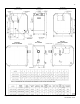
2. The expansion tank must be located as shown in Part 4, Section H, Piping Diagrams, or following recognized design methods. See
expansion tank manufacturer’s instructions for details. Always install an expansion tank designed for potable water systems.
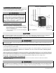
D. CIRCULATOR PUMPS
DO NOT install automatic air vents on closed type expansion tank systems. Air must remain in the system and return to the tank to
provide an air cushion. An automatic air vent would cause air to leave the system, resulting in improper operation of the expansion tank.
DO NOT use the boiler circulator in any location other than the ones shown in this manual. The boiler circulator location is selected to
ensure adequate flow through the boiler. Failure to comply with this caution could result in unreliable performance and nuisance
shutdowns from insufficient flow.