
Manual


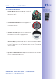


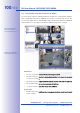
Table Of Contents
- Added Security Value
- Cost Benefits And Technical Advantages
- 2 INSTALLATION
- 3 OPERATING THE CAMERA
- 3.1 Manual And Automatic Operation - Overview
- 3.2 First Images And The Most Important Settings
- 3.3 Virtual PTZ
- 3.4 Correction Of Lens Distortion (L22 Only)
- 3.8 Additional Notes
- 3.8.1 Weatherproof Qualities
- 3.8.2 Password For The Administration Menu
- 3.8.3 Starting The Camera With The Factory IP Address
- 3.8.4 Reset The Camera To Factory Settings
- 3.8.5 Activate Event Control And Motion Detection
- 3.8.6 Deactivate Text And Logo Options
- 3.8.7 Deactivating The Daily Automatic Camera Reboot
- 3.8.8 Browser
- 3.8.9 Cleaning The Camera And Lens
- 3.8.10 Safety Warnings

www.mobotix.com • sales@mobotix.com
. This default is usually fine and nothing needs
to be changed. However, if the lower power level Class 1 is sucient for your application,
it may be advantageous – due to possible internal power distribution schemes amongst
the ports of the PoE switch in use – to change the PoE power level class in the browser:
1.
Select
(for experts).
2.
U
nder Power Supply, click Change.
3.
A
will appear to guide you through the PoE
configuration steps.
4.
T
he camera will then need to be restarted via a hard reboot:
, t hen recon-
, then recon -
nect it, for example, by disconnecting and then reconnecting
the network cable at the PoE switch.
1.
Connect
the factory pre-installed cable of the
camera to the
Camera
connector of the Network Power Adapter.
2.
C
onnect the
connector of the NPA to the switch/router or the Ethernet
connector of the NPA to the switch/router or the Ethernet
socket using an Ethernet connector.
3.
P
lug the RJ45 connector of the external power unit into the
connector
connector
of the Network Power Adapter.
Variable PoE: multiple
cameras can be oper-
ated simultaneously
from the same switch
For the D24M, you
should use the new
blue MX-NPA-PoE-Set
- previous MOBOTIX
network power acces-
sories such as the NPA
Set, Power Box and
Power Rack (MX-NPA-
Set, MX-NPR-4 and
MX-NPR8/20) are
not suitable for use
with the D24M
The IP addresses in
the diagram are shown
only as an example