
Manual
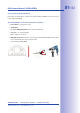


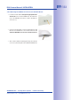

Table Of Contents
- Added Security Value
- Cost Benefits And Technical Advantages
- 2 INSTALLATION
- 3 OPERATING THE CAMERA
- 3.1 Manual And Automatic Operation - Overview
- 3.2 First Images And The Most Important Settings
- 3.3 Virtual PTZ
- 3.4 Correction Of Lens Distortion (L22 Only)
- 3.8 Additional Notes
- 3.8.1 Weatherproof Qualities
- 3.8.2 Password For The Administration Menu
- 3.8.3 Starting The Camera With The Factory IP Address
- 3.8.4 Reset The Camera To Factory Settings
- 3.8.5 Activate Event Control And Motion Detection
- 3.8.6 Deactivate Text And Logo Options
- 3.8.7 Deactivating The Daily Automatic Camera Reboot
- 3.8.8 Browser
- 3.8.9 Cleaning The Camera And Lens
- 3.8.10 Safety Warnings

www.mobotix.com • sales@mobotix.com
Use the supplied stainless steel straps to ax the Corner and Pole Mount to a pole.
•
Guide
the supplied
stainless steel straps
through the
openings in the Corner and Pole Mount as shown in
the diagram. Make sure that you are using the slots of
the mount that best fit for the thickness of the pole. The
stainless steel straps allow attaching the mount to poles
with diameters between 60 and 180mm.
•
Guide the on-site network cable from behind through
one
of the large round holes of the Corner and Pole
Mount. In order to properly protect the cabling, it is best
to pass the cabling from the inside of the pole through
the Corner and Pole Mount directly into the camera
(concealed cabling).
•
stainless steel straps on the Pole Mount
with a screwdriver. If necessary, the ends of the straps
can be cut o.