
Manual

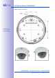
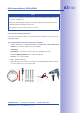
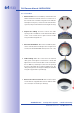
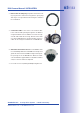
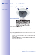


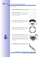
Table Of Contents
- Added Security Value
- Cost Benefits And Technical Advantages
- 2 INSTALLATION
- 3 OPERATING THE CAMERA
- 3.1 Manual And Automatic Operation - Overview
- 3.2 First Images And The Most Important Settings
- 3.3 Virtual PTZ
- 3.4 Correction Of Lens Distortion (L22 Only)
- 3.8 Additional Notes
- 3.8.1 Weatherproof Qualities
- 3.8.2 Password For The Administration Menu
- 3.8.3 Starting The Camera With The Factory IP Address
- 3.8.4 Reset The Camera To Factory Settings
- 3.8.5 Activate Event Control And Motion Detection
- 3.8.6 Deactivate Text And Logo Options
- 3.8.7 Deactivating The Daily Automatic Camera Reboot
- 3.8.8 Browser
- 3.8.9 Cleaning The Camera And Lens
- 3.8.10 Safety Warnings

www.mobotix.com • sales@mobotix.com
1.
: Run the network cable above the suspended
ceiling and ensure that enough cable slack is available.
2.
: Cut a round hole for cam-
era installation (e.g. with a 150 mm hole saw). Use the
supplied cutting template of the In-Ceiling Set (fold-out
at the end of the manual).
3.
: Remove all four Allen
screws using the supplied Allen wrench and lift o the
outer shell (not mounted upon delivery).
4.
: Separate the mounting
ring from the camera housing. This ring is not required
to mount the camera in the In-Ceiling Set.
5.
: The dovetail
guides at the back of the camera housing fit exactly
into the openings of the In-Ceiling mounting ring. To
make the camera even more secure (e.g. for mobile
use), push the four clamps (item 3.4) into the square
notches above the dovetail guides until you hear them
click into place.
6.
: Connect the on-site network cable to
the camera network cab l e using a s tandard co n nector.