
Specifications


72 Pure Data essentials
block, normally every 64 samples. Move it up and down quickly and listen to
the result. Fading is not perfectly smooth. You will hear a clicking sound when
you move the slider. This zipper noise is caused by the level s uddenly jumping
to a new value on a block boundary.
Using a log law fader
*~
dac~
0.5
osc~ 40
fig 7.3: log
level contr ol
The behaviour of slider objects can be changed. If you set its
properties to log instead of linear then smaller values are spread
out over a wider range and larger values are squashed into the
upper part of the movement. This gives you a finer degree of
control over level and is how most real mixing desks work. The
smallest value the slider will output is 0.01. With its top value as
1.0 it will also output 1.0 when fully moved. Between these values
it follows a logarithmic curve. When set to halfway it outputs a
value of about 0.1 and at three quarters of full movement its output is a little
over 0.3. It doesn’t rea ch an output of 0.5 until nearly nine tenths of its full
movement (shown in Fig. 7.3). This means half the output range is squashed
into the final ten percent of the movement range , so b e careful when you have
this log law fader connected to a loud amplifier. Often log law faders are limited
to constrain their range, which can be done with a
clip
unit.
MIDI fader
*~
dac~
0
0
osc~ 220 / 127
fig 7 .4: Scaling a
level
You won’t always want to control a mix from Pd GUI slid-
ers, sometimes you might wish to use a MIDI fader board or
other external control surface. These generally provide a lin-
ear control signal in the range 0 to 127 in integer steps, which
is also the default range of GUI sliders. To convert a MIDI
controller message into the range 0.0 to 1.0 it is divided by 1 27
(the same a s multiplying by 0.0078745) as shown in Fig. 7.4.
The nor malised output can be further scaled to a log curve, or multiplied by
100 to obtain a decibel scale and converted via the
dbtorms
object.
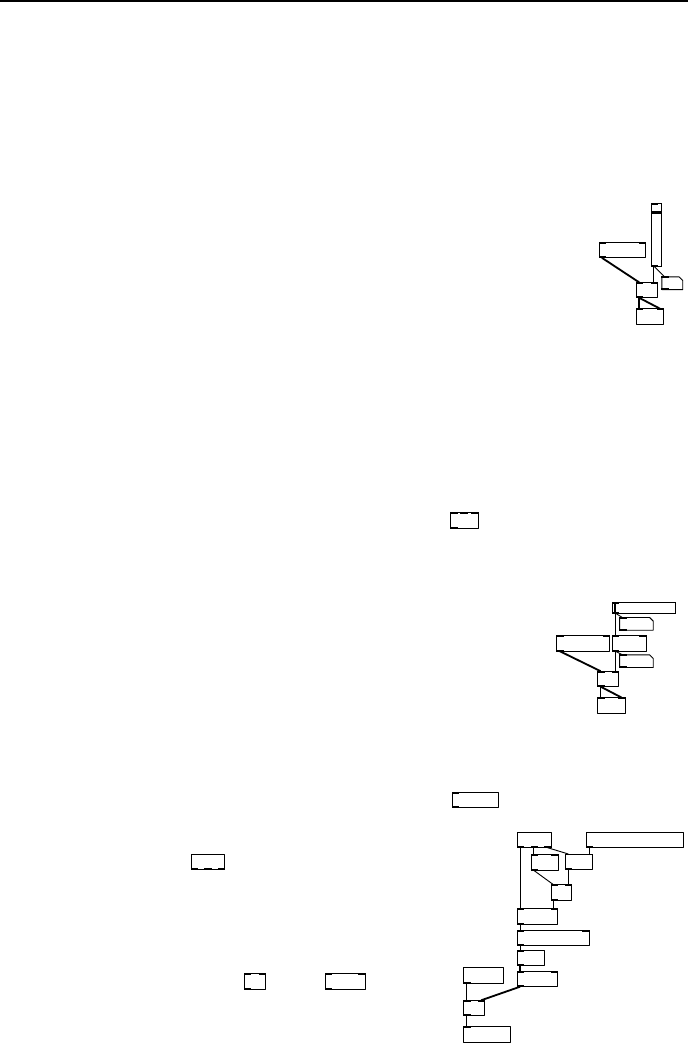
*~
* 0.0078745
ctlin
== 1
&&
spigot
== 7
sig~
lop~ 2
inlet~
outlet~
inlet midi-chan
fig 7.5: MIDI level
To connect the fader to an external MIDI device
you need to add a
ctlin
object. The fir st out-
let gives the current fader va lue, the second in-
dicates the continuous controller number and the
third provides the current MIDI channel. Volume
messages are sent on controller number 7. We
combine the outlets using
==
and
spigot
so that
only volume control messages on a particular chan-
nel are passed to the fader. The patch shown in
Fig. 7.5 has an audio inlet and outlet. It has an in-
let to set the MIDI channel. It can be subpatched
or abstracted to form one of several components in a complete MIDI c ontrolled
fader board.