
Specifications


66 Shaping sound
Phase cancellation
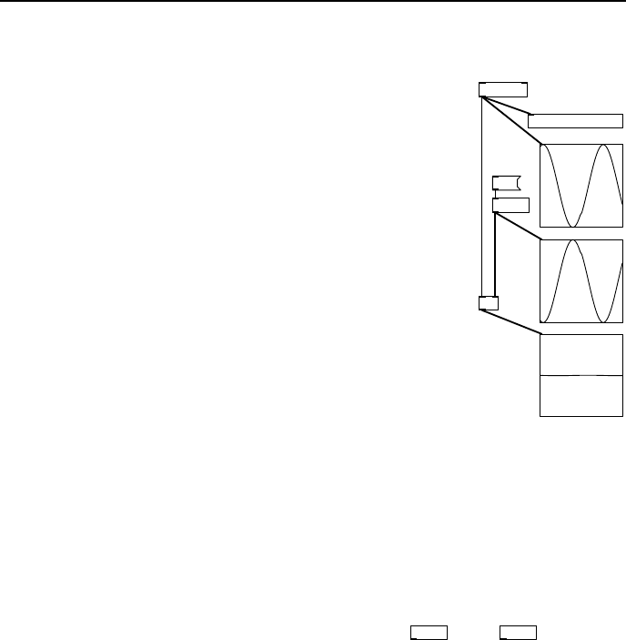
+~
osc~ 312
1.6
vd~ d1
delwrite~ d1 200
pd grapha
C
pd grapha
B
pd grapha
A
fig 6.18: Antiphase
Assuming that two adjacent cycles of a periodic waveform
are largely the same then if we delay that periodic signal
by time equal to half its period we have changed its phase
by 180
◦
. In the patch shown here the two signals are out
of phase. Mixing the original signal back with a copy that
is anti-phase annihilates both signals leaving nothing. In
Fig. 6.18 a sinusoidal signal at 312Hz is sent to a delay d1.
Since the input frequency is 312Hz its period is 3.2051ms,
and half tha t is 1.60256ms. The delayed signal will be
out of phase by half of the input signal period. What
would happ e n if the delay were set so that the two signals
were perfectly in phase? In that case instead of being
zero the output would b e a waveform with twice the input
amplitude. For delay times between these two cases the
output amplitude varies between 0.0 and 2.0. We can say
for a g iven frequency component the output amplitude
depends on the delay time. However, let’s assume the
delay is fixed and put it another way - fo r a given delay
time the output amplitude depends on the input frequency. What we have
created is a simple filter.
Filters
When delay time and period coincide we call the loud part (twice the input
amplitude) created by reinforcement a pole, and when the delay time equals
half the period we call the quiet part where the waves cancel out a zero. Very
basic but flexible filters are provided in Pd called
rpole~
and
rzero~
. They are
tricky to set up unless you learn a little more about DSP filter theory because
the frequencies of the poles or zeros are determined by a normalised number
that repres e nts the range of 0Hz to SR/2 Hz, where SR is the sampling rate
of the patch. Simple filters can be understood by an equation governing how
the output samples are computed as a function of the curre nt or past samples.
There are two kinds, thos e w hose output depends only on past va lues of the
input, which are called finite impulse response filters (FIR), and another type
whose output depends on past input values and on past output values. In other
words this kind has a feedback loop around the delay elements. Because the
effect of a signa l value could theoretically circulate forever we call this kind
recursive or infinite impulse response filters (IIR).
User friendly filters
Filters may have many poles and zeros but instead of calculating these from
delay times, sampling rates and wave periods we prefer to use filters designed
with preset behaviours. The behaviour of a filter is determined by a built in
calculator that works out the coefficients to set poles, zero s and feedback levels
for one or more internal delays. Instead of poles and ze ros we use a different