
Specifications


40 Pure Data Audio
Audio object CPU use
All the message objects we looked at in the last chapters only use CPU when
event driven dataflow occurs, so most of the time they sit idle and consume
no resources. Many o f the boxes we put on our sound design canvases will be
audio objects, so it’s worth noting that they use up some CPU power just being
idle. Whenever compute audio is switched on they are processing a constant
stream of signal blocks, even if the blocks only contain zero s. Unlike messages
which are processed in logical time, signals are processed synchronously with
the soundcard sample rate. This real-time cons traint means glitches will occur
unless every s ignal object in the patch can be computed before the next block
is sent out. P d will not simply give up when this happens, it will s truggle
along trying to maintain real-time processing, so you need to listen carefully,
as you hit the CPU limit of the computer you may hear crackles or pops. It is
also worth knowing how audio computation rela tes to messages computation.
Messages opera tions are executed at the beginning of each pass of audio block
processing, so a patch where audio depends on message opera tions which don’t
complete in time will also fa il to produce correct output.
SECTION 4.2
Audio objects and principles
There are a few ways that audio objects differ from message objects so let’s
look at those rules now before starting to create sounds.
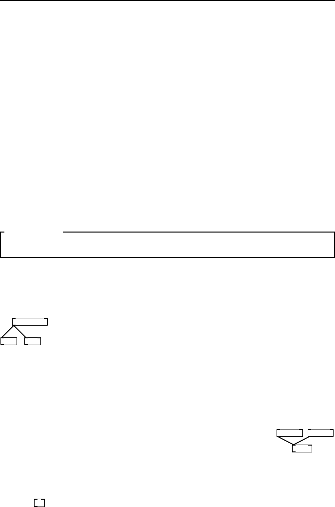
Fanout and merging
phasor~ 440
wrap~ *~ -1
fig 4.2: Sig-
nal fanout is
Okay.
You can connect the same signal o utlet to as many other audio
signal inlets as you like, and blocks are sent in an order which
corresponds to the creation of the connections, much like message
connections. But unlike messages, most of the time this will have
no effect whatsoever, so you can treat audio signals that fan out
as if they were perfect simultaneous copies. Very seldom you may
meet rare and interesting problems, especially with delays and feedback, that
can be fixed by reordering audio signals (see Chapter 7 of Puckette, “Theory
and technique” regarding time shifts and block delays).
osc~ 120 osc~ 240
*~ 0.5
fig 4.3: Merg-
ing signals is
Okay.
When several signal connections a ll come into the same
signal inlet that’s also fine. In this case they are implicitly
summed, so you may nee d to scale your signal to reduce its
range a gain at the output of the object. You can connect as
many signals to the same inlet as you like, but sometimes it
makes a patch easier to understand if you ex plicitly sum them
with a
+~
unit.
Time and resolution
Time is measured in seconds, milliseconds (one thousandth of a second, wr it-
ten 1ms) or samples. Most Pd times are in ms. Where time is measured in