
User's Manual

U S E R M A N U A L
SPEC NO
SHT/SHTS 3/4
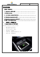
1.2 System overview
Wireless charging controller <LP, MP> - System for charging mobile phone wirelessly in
vehicle using electromagnetic induction between coils
① After inputting IGN1 power, the reception coil (cell phone RX Coil)
② Confirmation of non-mobile NFC mounting via NFC Multi Tagging <MP + NFC>
③ (TX side charging pad: wireless charger side) Current flows in the transmission coil
④ The magnetic field generated by the current of the transmission coil is guided to the
receiving coil and induction current is generated in the receiving coil
⑤ The charging current starts to be charged through PMIC (Power module IC) of mobile phone
NFC Communication Controller <MP + NFC> - Vehicle start, key registration, and vehicle information
transmission / reception device through mutual communication with NFC (near field communication)
installed in mobile phone and ECU.
① After inputting B + power, put Smart Phone on top of ECU
② When charging C_WPCNFCCmd = 0x01 (NFCSearchingOnHCE) from the authentication unit, stop wireless
charging && NFC Start
③ PhoneKeyAuth Mode (SmartPhone ↔ WPC ↔ IAU AUTH certification)
④ RTC SYNC MODE (RTC synchronization)
⑤ CertificateChain SYNC MODE (Certificate Synchronization)
⑥ PhoneKey Sync MODE MODE (Synchronize PhoneKey and Spare Key)
⑦ When C_WPCNFCCmd = 0x02 (NFC Searching Off) is input from the authentication unit NFC Mode Stop &&
When IGN1 is ON,
Wireless charging Start
2 ELECTRICAL CHARACTERISTICS
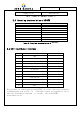
2.1 Operating characteristics of MP
Item Specification
Rated Supply Voltage DC 12V
Operating Voltage DC 9 ~ 16V
Operating Temperature - 30 ~ + 75℃
Storage temperature range - 40 ~ + 85℃
MP<WPC> Frequency
115kHz