
Instruction manual
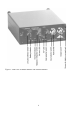
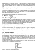

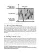
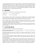

Figure 5: Dynamic range of IEPE compatible transducers
4.2.1. Switching Off the IEPE Supply
In some cases it may be necessary to switch off the constant current supply, in order to use the
input for normal AC sources. For this purpose, please change the position of the jumper, which
you will find at Models M68D1 and M68R1 behind the front panel. Remove the cover of Model
M68D1 by unscrewing the four plastic screw heads. To remove the cover of Model M68R1,
four screws at the side and two at the back are unscrewed. Jumper J1 is located left at the front
side of the printed circuit board. Plug it into the position “OFF” to switch off the constant cur-
rent source.
After removing the front cover of Model M68D3 you will see only the jumper of channel 1. To
reach the jumpers of channels 2 and 3, please remove front and rear panel.
5. Avoiding Ground Loops
Earthing or ground loops are often the reason for measuring errors in multichannel measuring
systems. In most cases you will find a superimposed 50 Hz or 100 Hz voltage on the measuring
signal. One reason for this effect may be, that the transducers are connected to ground not only
via their cable at the signal conditioner, but also in addition at the measuring point through their
case. Vibration transducers are often mounted at grounded machine parts. Within earthing sys-
tems transient currents may appear. These transient currents cause a potential drop across the
earthing or grounding wires. Via the signal input of the amplifier they may result in a considera-
ble measuring error.
To avoid this, insulated attachment of the transducers is recommended.
Metra offers several industrial vibration transducers with insulated mounting base and different
insulating flanges for non-insulated sensors.
9
Max. output voltage =
supply voltage of
constant current source
Min. output voltage =
saturation voltage
(see data sheet)
Sensor bias voltage
(see data sheet)
negative overload
0V
positive overload
24 V
0.5..1 V
5 .. 14 V