
Instruction manual


A peculiarity of IEPE is, that power supply and measuring signal use the same line. So, an
IEPE
transducer needs, like a transducer with charge output, only one single-ended line.
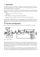
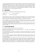
Figure 4 shows the circuit diagram. To separate the low impedance sensor signal from the power
supply, the integrated circuit is supplied with constant current.
This constant current must be fed into the measuring line and simultaneously separated from the
following amplifier stages. The yellow LED “IEPE ON” indicates the flow of constant current.
By supplying the sensor with constant current a positive DC voltage arises over its terminals.
This static bias voltage depends on manufacturer and specimen and amounts to about 5 through
14 V. The sensor signal is superposed on this bias voltage. The output voltage of the transducer
never changes to negative values. Its minimum value is the saturation voltage of the integrated
impedance converter (0.5 V to 1 V). The supply voltage of the constant current source determi-
nes the maximum value of the output voltage. For the M68 this voltage amounts up to 24 V and
guarantees an optimum dynamic range for all available sensors.Figure 5 shows these relations.
8
Figure 4: IEPE principle
Integrated amplifier
U
I
const
s
Q
U
Piezo
ceramics
C
C
R
I
C
C
I
const
R
I
Coupling capacitor
Constant supply current
Input resistance
U
s
Supply voltage of
constant current source
coaxial cable,
> 100 m
IEPE Transducer Signal Conditioner